Bounding box gesture recognition on a touch detecting interactive display

a gesture recognition and interactive display technology, applied in the field of interactive displays, can solve the problems of difficult methods, impractical or prohibitively expensive incorporation into large interactive displays, and inability to scale well of capacitive sensors, and achieve the effect of high reliability

Active Publication Date: 2006-12-21
QUALCOMM INC
View PDF67 Cites 85 Cited by
  • Summary
  • Abstract
  • Description
  • Claims
  • Application Information

AI Technical Summary

Benefits of technology

[0010] The invention provides a method and apparatus for identifying gestures performed by a user to control an interactive display. The gestures are identified based on a bounding box enclosing the points at which a user contacts a touch sensor corresponding with the display surface. The invention thus permits the use of inexpensive and highly reliable grid-based touch sensors that provide a bounding box to describe contact information. In identifying the gestures, the position, motion, shape, and deformation of the bounding box may all be considered. In particular, the center, width, height, aspect ratio, length of the diagonal, and orientation of the diagonal of the bounding box may be determined. A stretch factor, defined as the maximum of the ratio of the height of the bounding box to the width of the bounding box and the ratio of the width of the bounding box to the height of the bounding box, may also be computed. Finally, gestures may be identified based on the changes in time of these characteristics and quantities.
[0011] Gestures that may be identified include pan, zoom, and rot

Problems solved by technology

However, capacitive sensors do not scale well, and are therefore impractical or prohibitively expensive for incorporation into large interactive displays.
Clearly,

Method used


Image

  • Bounding box gesture recognition on a touch detecting interactive display
  • Bounding box gesture recognition on a touch detecting interactive display
  • Bounding box gesture recognition on a touch detecting interactive display

Examples


Embodiment Construction

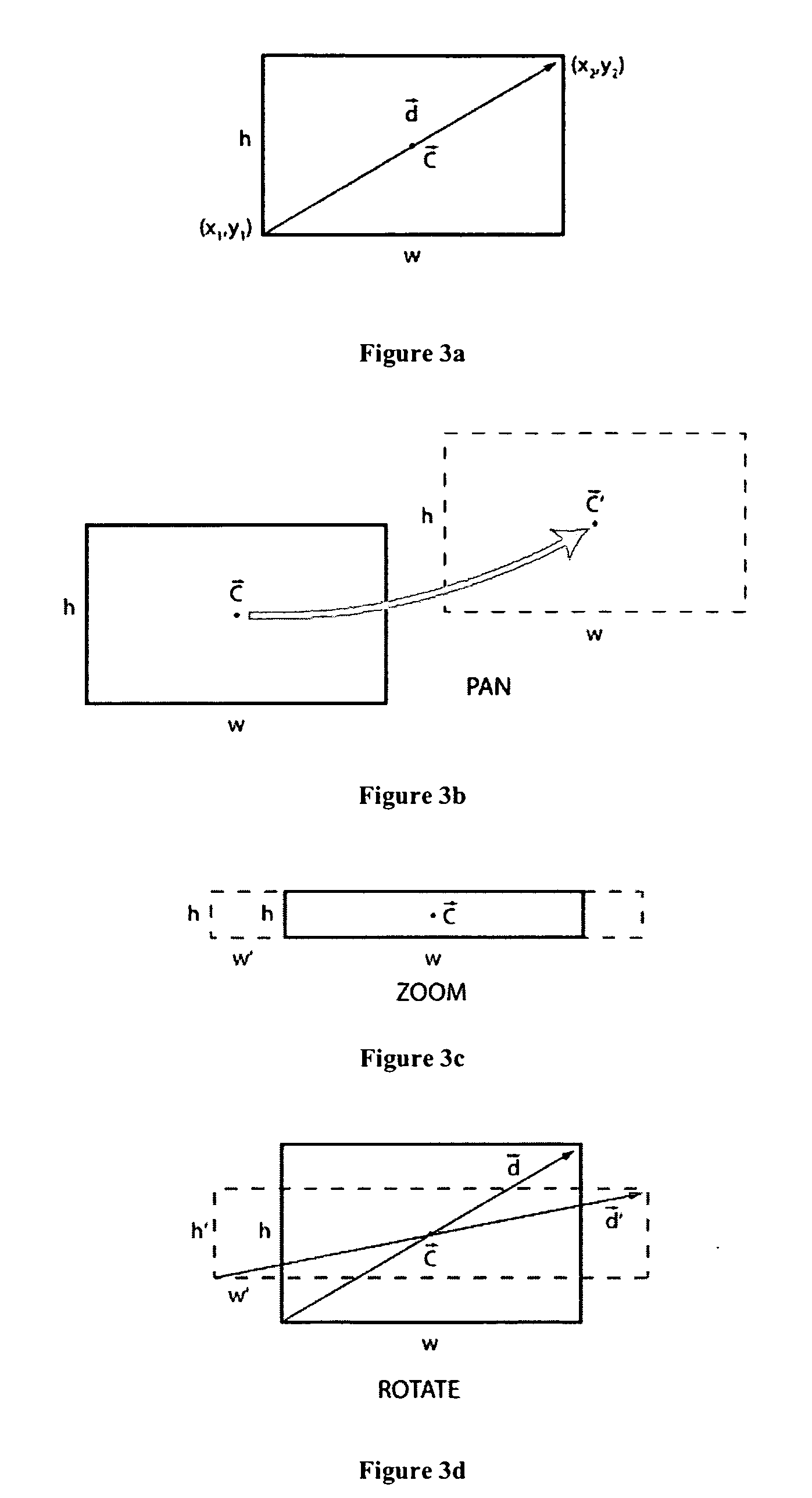
[0015] The invention provides a method and apparatus for identifying gestures performed by a user to control an interactive display. The gestures are identified based on a bounding box enclosing the points at which a user contacts a touch sensor corresponding with the display surface. The invention thus permits the use of inexpensive and highly reliable grid-based touch sensors that provide a bounding box to describe contact information.

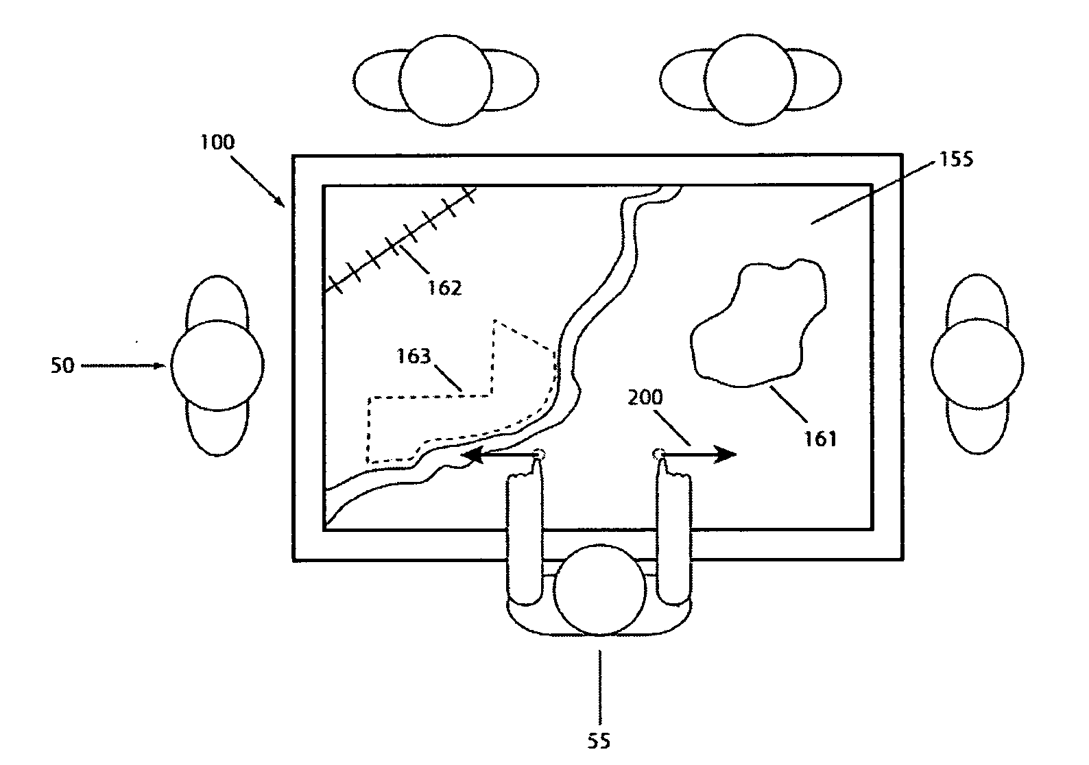
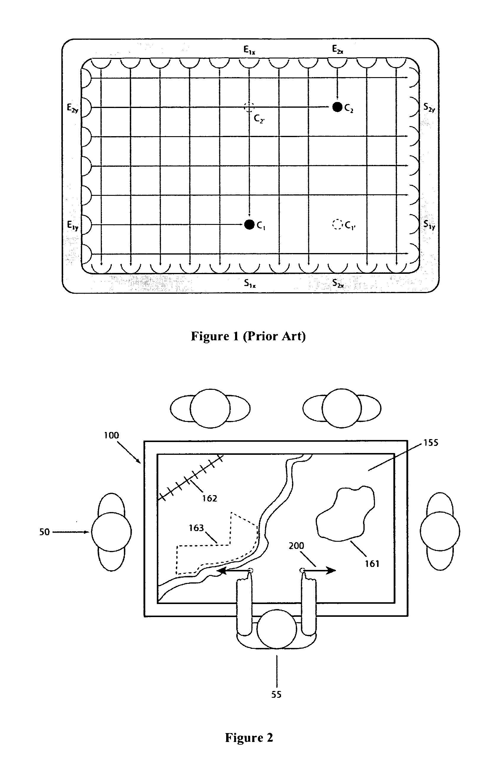
[0016]FIG. 2 shows is a schematic diagram that shows several users operating an exemplary interactive display in which the invention may be used. The users 50 surround the display 100 such that each can view the display surface 150, which shows imagery of interest to the users. For example, the display may present Geographic Information System (GIS) imagery characterized by geographic 161, economic 162, political 163, and other features, organized into one or more imagery layers. Because the users can comfortably surround and view the display, group...


PUM


Abstract

The invention provides a method and apparatus for identifying gestures performed by a user to control an interactive display. The gestures are identified based on a bounding box enclosing the points at which a user contacts a touch sensor corresponding with the display surface. The invention thus permits the use of inexpensive and highly reliable grid-based touch sensors that provide a bounding box to describe contact information. In identifying the gestures, the position, motion, shape, and deformation of the bounding box may all be considered. In particular, the center, width, height, aspect ratio, length of the diagonal, and orientation of the diagonal of the bounding box may be determined. A stretch factor, defined as the maximum of the ratio of the height of the bounding box to the width of the bounding box and the ratio of the width of the bounding box to the height of the bounding box, may also be computed. Finally, gestures may be identified based on the changes in time of these characteristics and quantities.

Description

RELATED APPLICATIONS [0001] This application is related to U.S. patent application Ser. No. 10 / 913,105, entitled Touch Detecting Interactive Display, filed 2004-08-06, the entirety of which is incorporated herein by this reference thereto.BACKGROUND [0002] 1. Technical Field [0003] The invention relates to interactive displays. More particularly, the invention relates to a method and apparatus for determining user gestures to control a touch detecting, interactive display. [0004] 2. Description of the Prior Art [0005] There are many situations in which one or more individuals interactively explore image-based data. For example, a team of paleontologists may wish to discuss an excavation plan for a remote dig site. To do so, they wish to explore in detail the geographic characteristics of the site as represented on digitized maps. In most laboratories, this requires the team either to huddle around a single workstation and view maps and images on a small display, or sit at separate w...

Claims


Application Information

Patent Timeline
IPC IPC(8): G06F3/00G09G5/00
CPCG06F3/04883G06F3/0488G06F2203/04808G06F2203/04806
Inventor HILLIS, W. DANIEL
Owner QUALCOMM INC
Why Eureka
Try Eureka