
Collapsible rake

a rake and collapsible technology, applied in hand equipment, agriculture tools and machines, agriculture, etc., can solve the problems of too large prongs or tines, rakes are not easily carried on hiking and camping excursions, and the frame to which the prongs or tines are attached is too large to be conveniently carried in small spaces

Inactive Publication Date: 2007-11-27
SANDERS JAMES
View PDF21 Cites 12 Cited by
  • Summary
  • Abstract
  • Description
  • Claims
  • Application Information

AI Technical Summary

Benefits of technology

"The present invention provides a rake that includes at least two tine frames with a plurality of tines, a tine frame coupling, pivot mechanisms, a rake handle, and a locking mechanism. The tine frames can be locked into an operational raking configuration or unlocked for transition to a non-raking stowage configuration. When unlocked, the tine frames can be pivoted towards the rake handle with their distal ends close to the handle. The technical effect of this invention is to provide a rake that can be easily stored and transported without needing to fully extend the tines, while still being able to effectively rake."

Problems solved by technology

Rakes and other similar implements used for lawn and land management activities, while often simple to operate, reliable, and reasonably inexpensive, are often more bulky than desirable.
As a result, rakes are not easily carried on hiking and camping excursions where they might be needed a considerable distance from the automobile which has transported them.
Not only is a conventional handle an impediment to portability and stowability or storability in small spaces such backpacks, but the frames to which the prongs or tines are attached are also too large to be conveniently carried in small spaces.
As a result, the minimum practical handle length needed to accept the tines and the additional length often needed to accommodate rods or other mechanisms, make these rakes too long for small space storage-even when the handles are collapsible.
Such rakes are often complex and expensive.
Yet other approaches are also inadequate, including those disclosed by the U.S. Pat. Nos. 6,408,606, 5,598,691, 4,848,073, and U.S. patent application Ser. No. 2004 / 0088962.

Method used


Image

  • Collapsible rake
  • Collapsible rake
  • Collapsible rake

Examples


Embodiment Construction

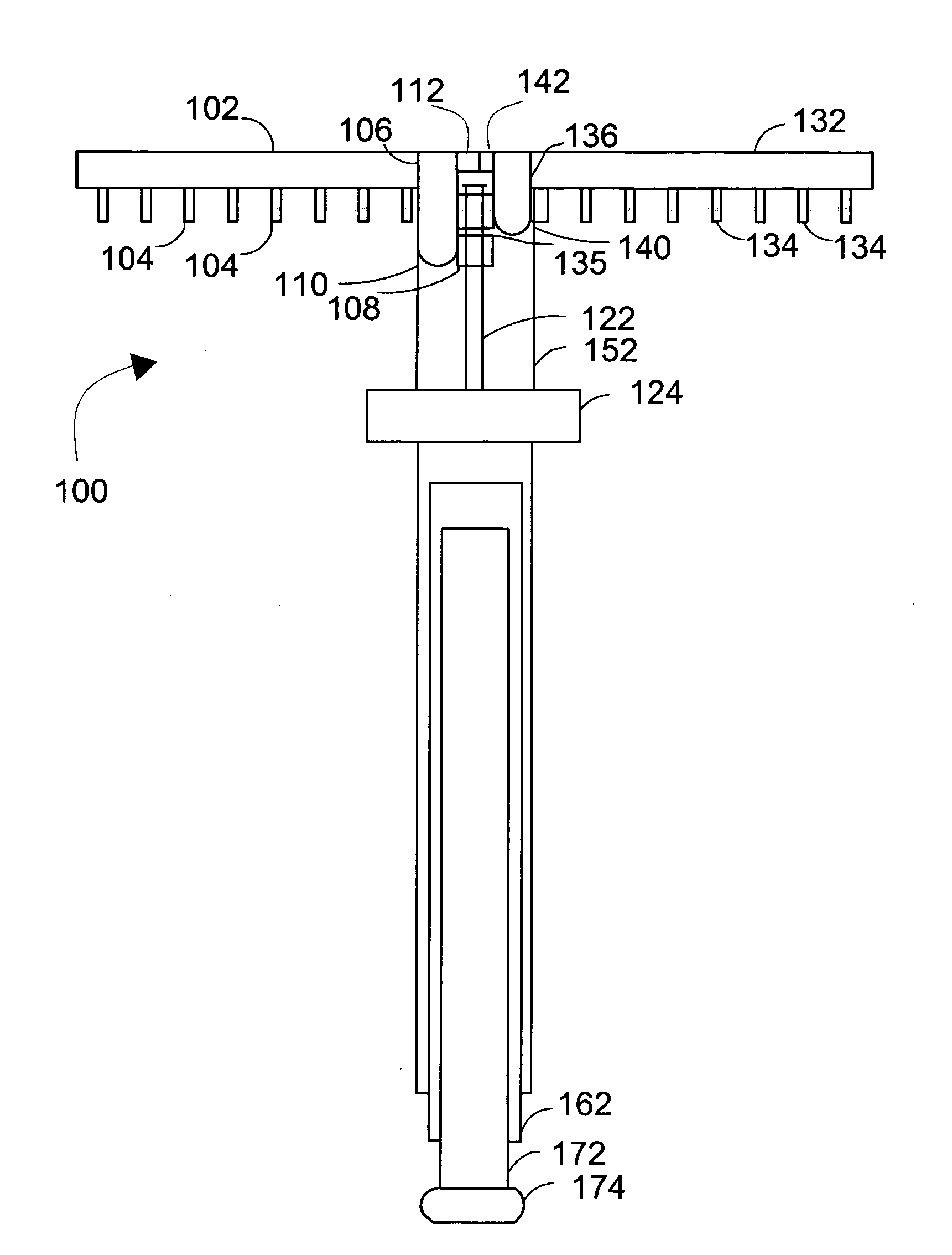
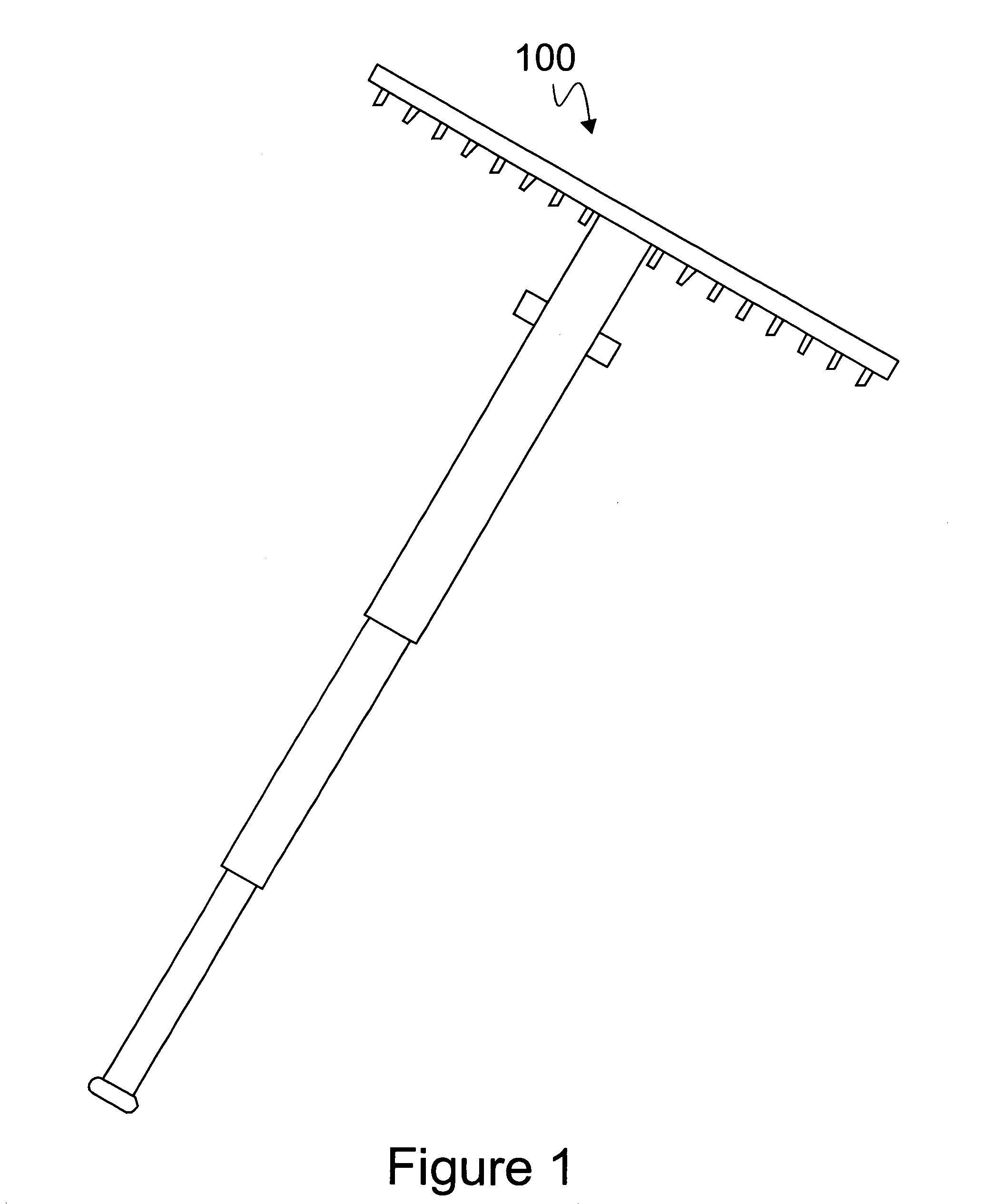
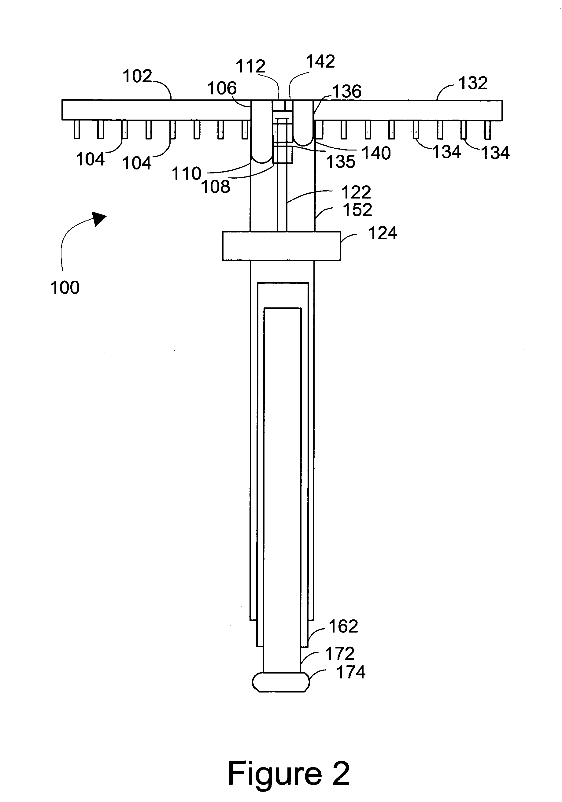
[0020]A view of a preferred embodiment of the present-inventive rake 100 is shown in FIG. 1. In general, the present-inventive rake 100 is full size in the raking configuration illustrated. Used below, the term “raking configuration” means a configuration of the rake that allows a user to engage in raking and similar activities. “Stowage configuration” and “storage configuration” refer to configurations of the rake where components are retracted, allowing for easier stowage, storage or transportation.

[0021]The tines and the frames to which they are attached are locked into position for raking, and unlocked for storage by pressing a tab and pulling the tine frames away from the rake handle, as will be explained infra. The rake handle is collapsible—in this case telescopic—to reduce the height of the rake for storage.

[0022]Turning to the cutaway view of FIG. 2, and the plan view of FIG. 3 (which shows the rake 100 axially rotated 90 degrees with respect to the illustration in FIG. 1),...


PUM


Abstract

A novel rake minimally consists of: at least two tine frames, each tine frame having a plurality of tines coupled thereto; a tine frame coupling for coupling to proximal ends of each of the tine frames; pivot mechanisms coupled between the tine frames and the tine frame coupling; a rake handle coupled at a proximal end to the tine frame coupling, and adapted for being grasped at a distal end for raking activity; and a locking mechanism adapted to lock the tine frames into an operational raking configuration, and adapted to unlock the tine frames for transition to a non-raking stowage configuration. When the tine frames are unlocked, the tine frames are adapted to have their distal ends pivoted toward the distal end of the rake handle into the stowage configuration with the distal ends of the tine frames being at least in close proximity of the rake handle.

Description

1. FIELD OF THE INVENTION[0001]The present invention generally relates to rakes and other manual implements used to comb land to gather material, or for loosening or smoothing land. More particularly, the present invention relates to improving the stowability and portability of rakes and similar implements which are suitable for use during camping activities.2. BACKGROUND OF RELATED ART[0002]Rakes and other similar implements used for lawn and land management activities, while often simple to operate, reliable, and reasonably inexpensive, are often more bulky than desirable. For example, in order to be durable, reliable, and practical, rake handles are typically too long to be stored in small spaces such as backpacks and luggage. As a result, rakes are not easily carried on hiking and camping excursions where they might be needed a considerable distance from the automobile which has transported them.[0003]Not only is a conventional handle an impediment to portability and stowability...

Claims


Application Information

Patent Timeline
Patent Type & Authority Patents(United States)
IPC IPC(8): A01D7/00
CPCA01D7/00
Inventor SANDERS, JAMES
Owner SANDERS JAMES
Learn More