Progressive safety device

a safety device and progressive technology, applied in the direction of elevators, transportation and packaging, etc., can solve the problems of false actuation of the progressive safety device, mechanical complexity the inability to adjust the speed of the speed governor, etc., to achieve the effect of easy actuation and easy res

Active Publication Date: 2007-11-27
INVENTIO AG
View PDF10 Cites 49 Cited by
  • Summary
  • Abstract
  • Description
  • Claims
  • Application Information

AI Technical Summary

Benefits of technology

[0008]The present invention concerns an apparatus that provides a solution for avoiding the disadvantages of the known device, and proposes a method of engaging a progressive safety device and creating a progressive safety device that is easily actuated in the downward and upward directions of travel and is easily reset.
[0009]The advantages achieved by means of the present invention are mainly that the progressive safety device can be actuated with few moving parts, as a result of which short response times can be realized. The spring needed for actuation can be kept small since only small masses have to be accelerated by the actuating spring. The progressive safety device is actuated in the upward and downward direction by the same parts, the braking force being generated by the movement of the elevator car. Resetting of the actuating parts takes place by means of the parts that brake the elevator car, the energy for resetting coming from the traveling motion of the elevator car. Manual release of the elevator car and the progressive safety device is not necessary.

Problems solved by technology

A disadvantage of the known device is that actuation of the progressive safety device takes place via the governor rope.
Rope oscillations in the governor rope that is stretched over the entire hoistway height can cause noises in the elevator car and lead to false actuation of the progressive safety device.
The speed governor is a mechanically complex fault-prone device that requires space in the hoistway headroom and in the hoistway pit.
A disadvantage of this known device is that, on actuation, the spring has to accelerate the pin and the actuating lever with the blocking roller arranged on the long lever of the actuating lever.
This results in long dead times until the effective braking of the elevator car.
Moreover, the safety device acts in only one direction and is only suitable for actuation at low speeds.

Method used


Image

  • Progressive safety device
  • Progressive safety device
  • Progressive safety device

Examples


Embodiment Construction

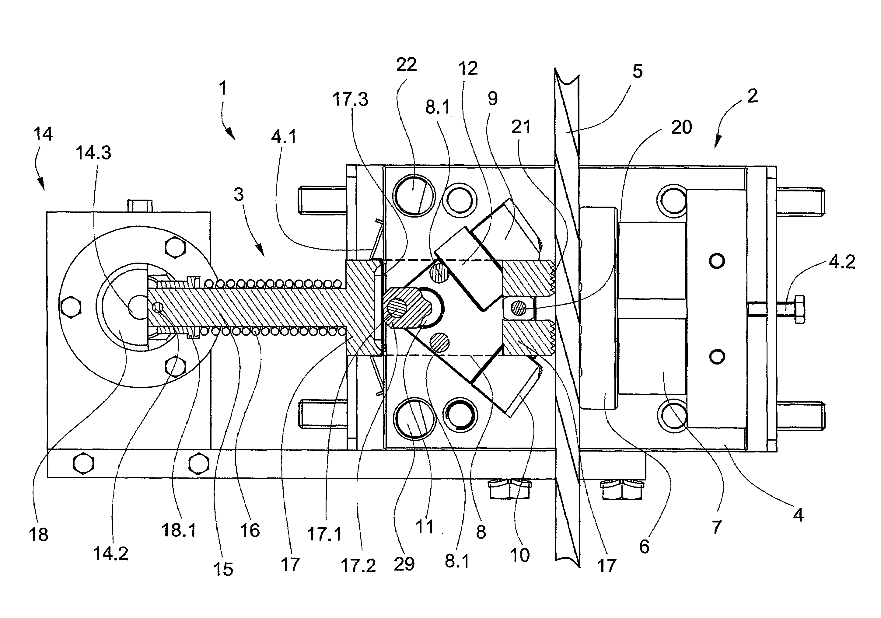
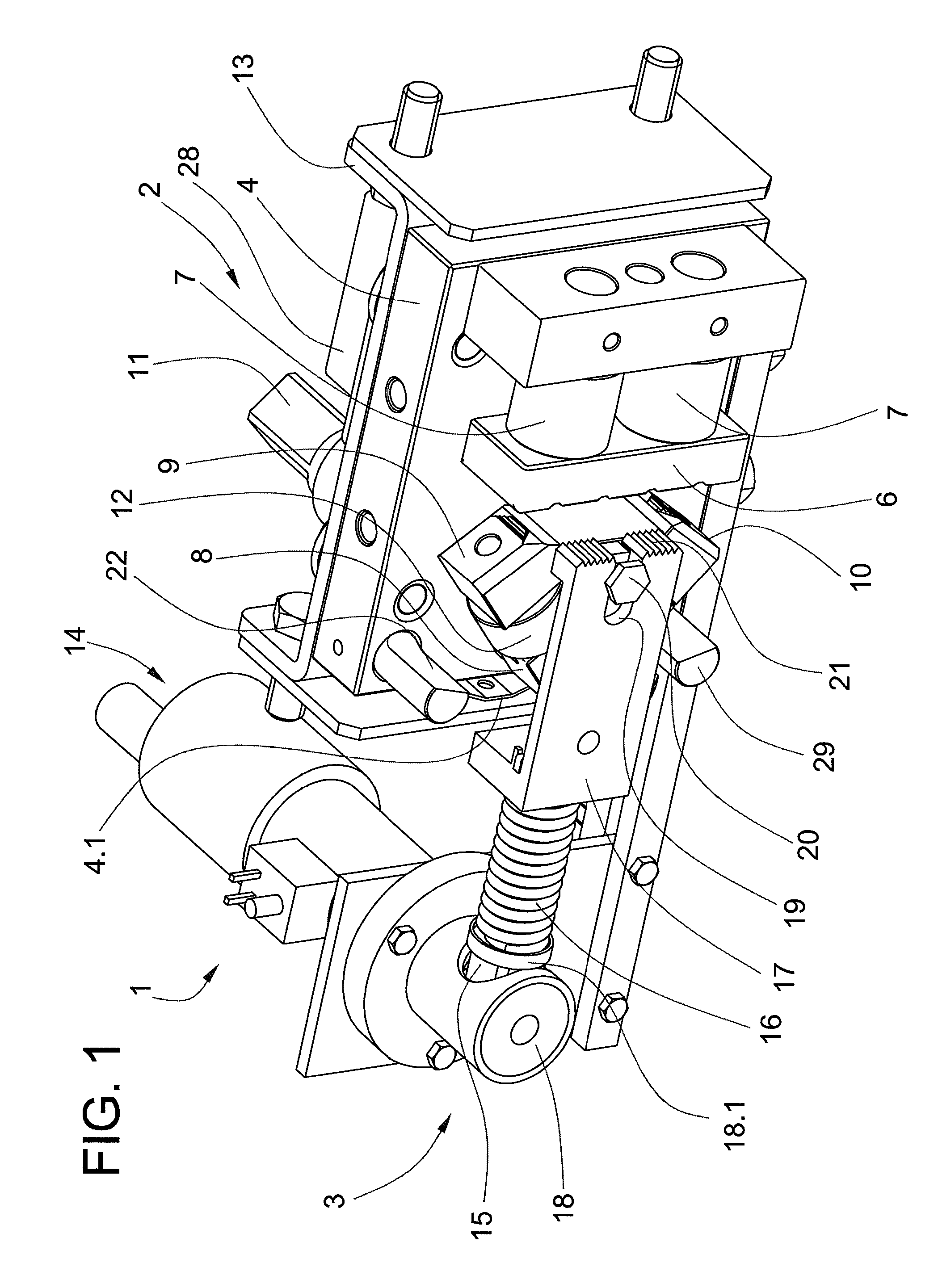
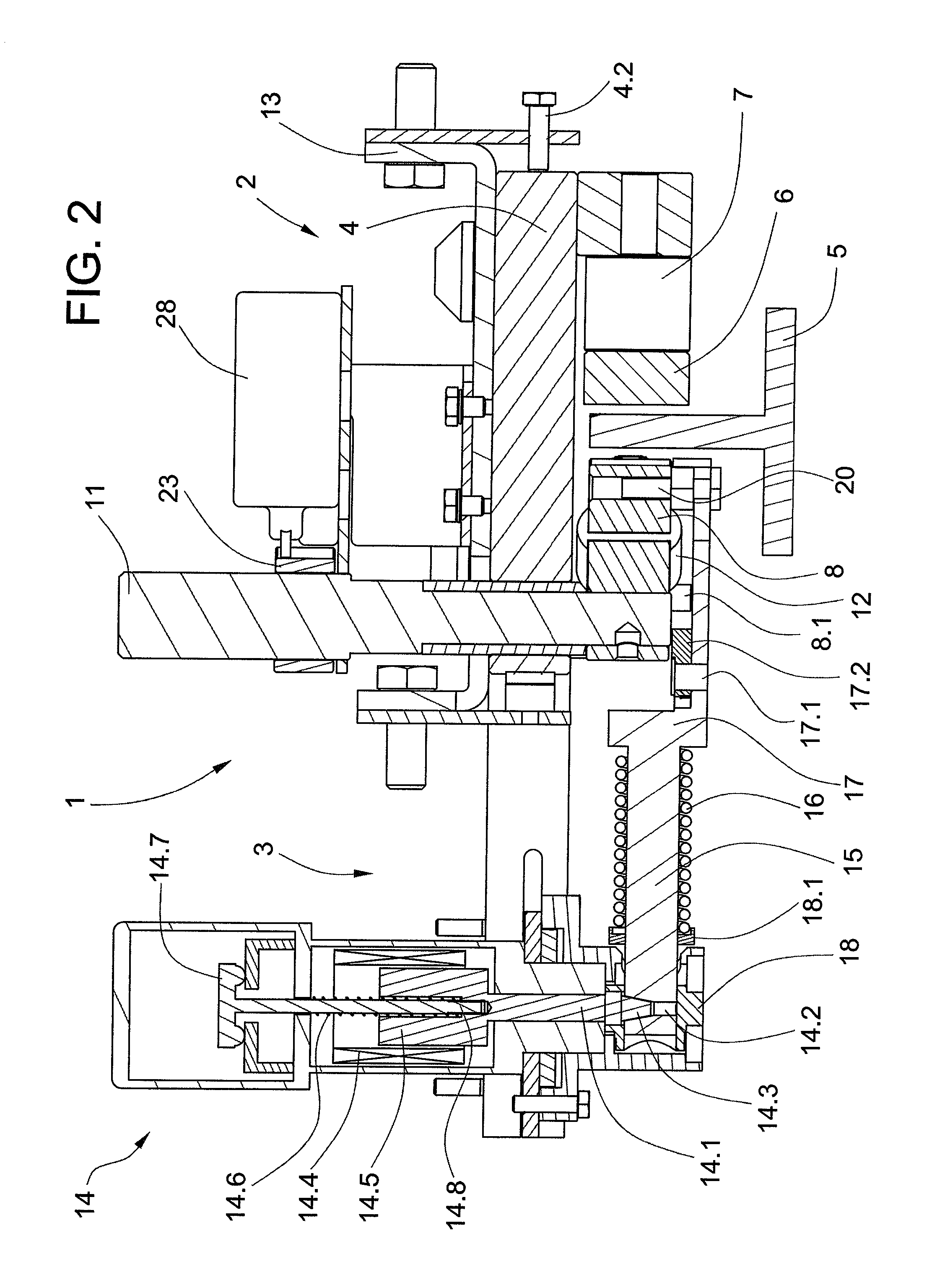
[0020]FIG. 1 shows a progressive safety device 1 according to the present invention comprising a brake unit 2 and an actuating unit 3. Provided for each guide rail 5 (FIG. 2) of the elevator car is the brake unit 2 that is arranged, for example, on the sling of the elevator car. The brake unit 2 is arranged on a base plate 4 that is held in its neutral position by means of a centering spring 4.1 and a centering screw 4.2 (FIG. 2). So that no constrained forces occur, the base plate 4 is held movably relative to a mounting plate 13 by means of bolts and elongated holes. By means of the centering screw 4.2 a rail play S (FIG. 3) is set.

[0021]The brake unit 2 consists essentially of a first brake shoe 6 arranged on the base plate 4 with first spring assemblies 7 and of a triangular rotatable support 8 (FIG. 2) with a second brake shoe 9 and with a third brake shoe 10, the support 8 of the first brake shoe 6 being arranged opposite the first brake shoe 6. The first corner of the support...


PUM


Abstract

A progressive safety device for an elevator includes a brake unit and an actuating unit. The brake unit has a first brake shoe with first spring assemblies and a triangular rotatable support with second and third brake shoes. The actuating unit has an electromagnetic actuator with a locking bolt, a guide bolt with a coaxial compression spring and an actuating arm. On actuation, the compression spring moves the actuating arm against a guide rail whereby grooves on the actuating arm create a frictional engagement with the guide rail turning the actuating arm about a swivel bearing and through a follower turning the support. With the turning motion and the engagement of one of the second and third brake shoes with the guide rail, the first brake shoe is guided against the guide rail and generates the necessary braking force on the guide rail.

Description

BACKGROUND OF THE INVENTION[0001]The present invention relates to a progressive safety device for an elevator, the elevator car and the counterweight being guided and movable on guide rails, the elevator car or the counterweight being arrestable on the guide rails by means of a braking unit with an actuating unit.[0002]The European Patent EP 1 283 189 B1 shows a progressive safety device for an elevator car. Arranged movably on a supporting element at right angles to a guide rail that guides the elevator car is a base plate. Arranged on the base plate is at least one actuating lever and opposite this a brake shoe. When the progressive safety device is actuated, the free end of the actuating lever comes into contact with the guide rail and is moved by the component of the frictional force that arises parallel to the guide rail, into the engaged position in which the guide rail is jammed between the free end of the actuating lever and the brake shoe.[0003]The actuating lever can be ac...

Claims


Application Information

Patent Timeline
Patent Type & Authority Patents(United States)
IPC IPC(8): B66B5/02B66B5/12
CPCB66B5/20B66B5/18B66B5/16B66B5/02
Inventor HUSMANN, JOSEF
Owner INVENTIO AG
Why Eureka
Try Eureka