Vehicle tire inflation system and sensor and method of use

a technology of tire inflation system and sensor, which is applied in the direction of tires, instruments, transportation and packaging, etc., can solve the problems of both lack of sensors and waste of valuable space at the wheel end

Inactive Publication Date: 2007-12-04
DANA HEAVY VEHICLE SYSTEMS GROUP LLC
View PDF20 Cites 49 Cited by
  • Summary
  • Abstract
  • Description
  • Claims
  • Application Information

AI Technical Summary

Problems solved by technology

The most obvious disadvantage of U.S. Pat. Nos. 5,287,906 and 6,668,888 is that both lack a sensor.
No. 5,327,346 does not efficiently package both a tire inflation system and a sensor so that valuable area at the wheel end is wasted.

Method used


Image

  • Vehicle tire inflation system and sensor and method of use
  • Vehicle tire inflation system and sensor and method of use
  • Vehicle tire inflation system and sensor and method of use

Examples


Embodiment Construction

[0013]It is to be understood that the invention may assume various alternative orientations and step sequences, except where expressly specified to the contrary. It is also to be understood that the specific devices and processes illustrated in the attached drawings, and described in the following specification are simply exemplary embodiments of the inventive concepts defined in the appended claims. Hence, specific dimensions, directions or other physical characteristics relating to the embodiments disclosed are not to be considered as limiting, unless the claims expressly state otherwise.

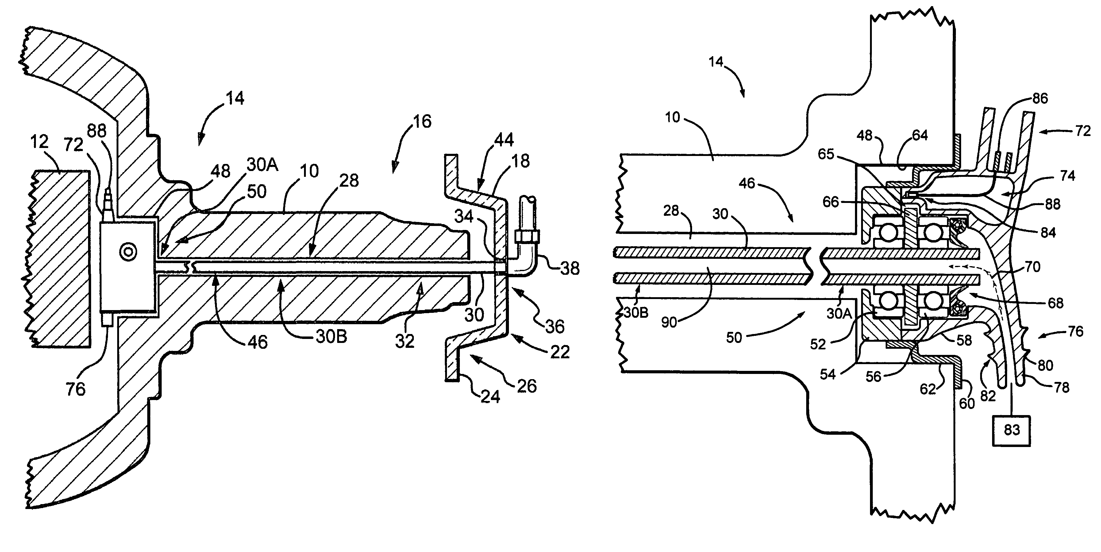
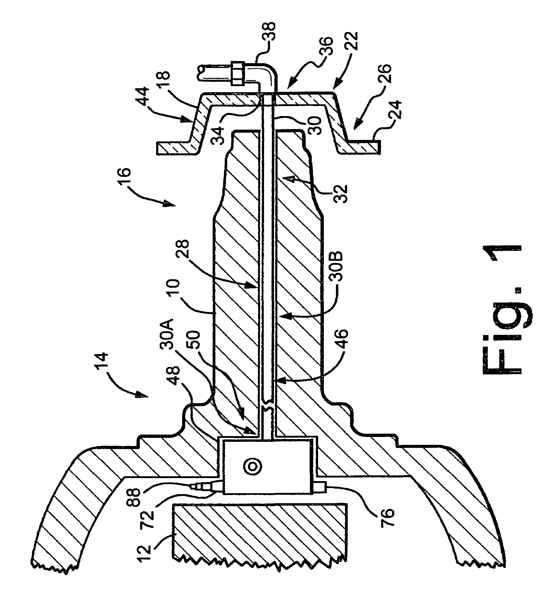
[0014]Referring now to FIG. 1, a spindle 10 associated with a steering axle 12 of a vehicle is schematically depicted. Only a portion of the steering axle 12 is depicted as the present invention is not limited to any particular steering axle and any steering axle may be used without departing from the scope of the present invention.

[0015]The spindle 10 may be connected to the axle 12 by any struct...


PUM


Abstract

A combined tire inflation system and a wheel speed sensor for a vehicle steer axle has a steerable spindle with a substantially hollow interior portion. A shaft, located in the hollow interior portion, connects a rotatable hub cap adjacent the spindle and a sensor at least partially within the spindle. A magnet is secured to the shaft and rotates with the shaft. A sensor is mounted adjacent the magnet for sensing the rotation of the magnet. The shaft has a hollow interior that connects an air source with a tire associated with the hub cap.

Description

FIELD OF THE INVENTION[0001]The present invention relates to a vehicle tire inflation system and sensor and method of use. More particularly, the present invention relates to a vehicle tire inflation system combined with an ABS wheel speed sensor for a steering axle.BACKGROUND OF THE INVENTION[0002]Various tire inflation systems for vehicles are well known to those skilled in the art. Wheel speed sensors to detect the wheel speed for various purposes, such the ABS system of the vehicle, are also well known, It is not generally well known, however, to combine a tire inflation system with a wheel speed sensor for a steering axle.[0003]For example, U.S. Pat. No. 5,287,906 teaches an air delivery system for vehicles. The patent only generally states that the system can be used for the front axle of a vehicle. In the embodiment of the invention depicted and described in the patent, the system comprises a fixed axle having a fixed air line extending therethrough. The fixed air line is con...

Claims


Application Information

Patent Timeline
Patent Type & Authority Patents(United States)
IPC IPC(8): B60C23/00G01P15/00
CPCG01P3/443B60C23/003B60C23/00363B60C23/00381B60C23/00318
Inventor DAVISON, KENT E.MOSES, DAVID G.STACER, DARYL J.
Owner DANA HEAVY VEHICLE SYSTEMS GROUP LLC
Why Eureka
Try Eureka