Vehicle control device and vehicle control method

a control device and vehicle technology, applied in the direction of braking systems, cycle equipment, instruments, etc., can solve the problem of lowering the accuracy of stroke speed estimation, and achieve the effect of avoiding deterioration of estimation accuracy

Active Publication Date: 2015-03-19
NISSAN MOTOR CO LTD
View PDF17 Cites 38 Cited by
  • Summary
  • Abstract
  • Description
  • Claims
  • Application Information

AI Technical Summary

Benefits of technology

[0008]Therefore, it can be detected that the sprung mass state estimation accuracy has deteriorated,

Problems solved by technology

However, a problem encountered in the aforementioned prior art is that when a disturbance of wheel speed

Method used


Image

  • Vehicle control device and vehicle control method
  • Vehicle control device and vehicle control method
  • Vehicle control device and vehicle control method

Examples


first embodiment

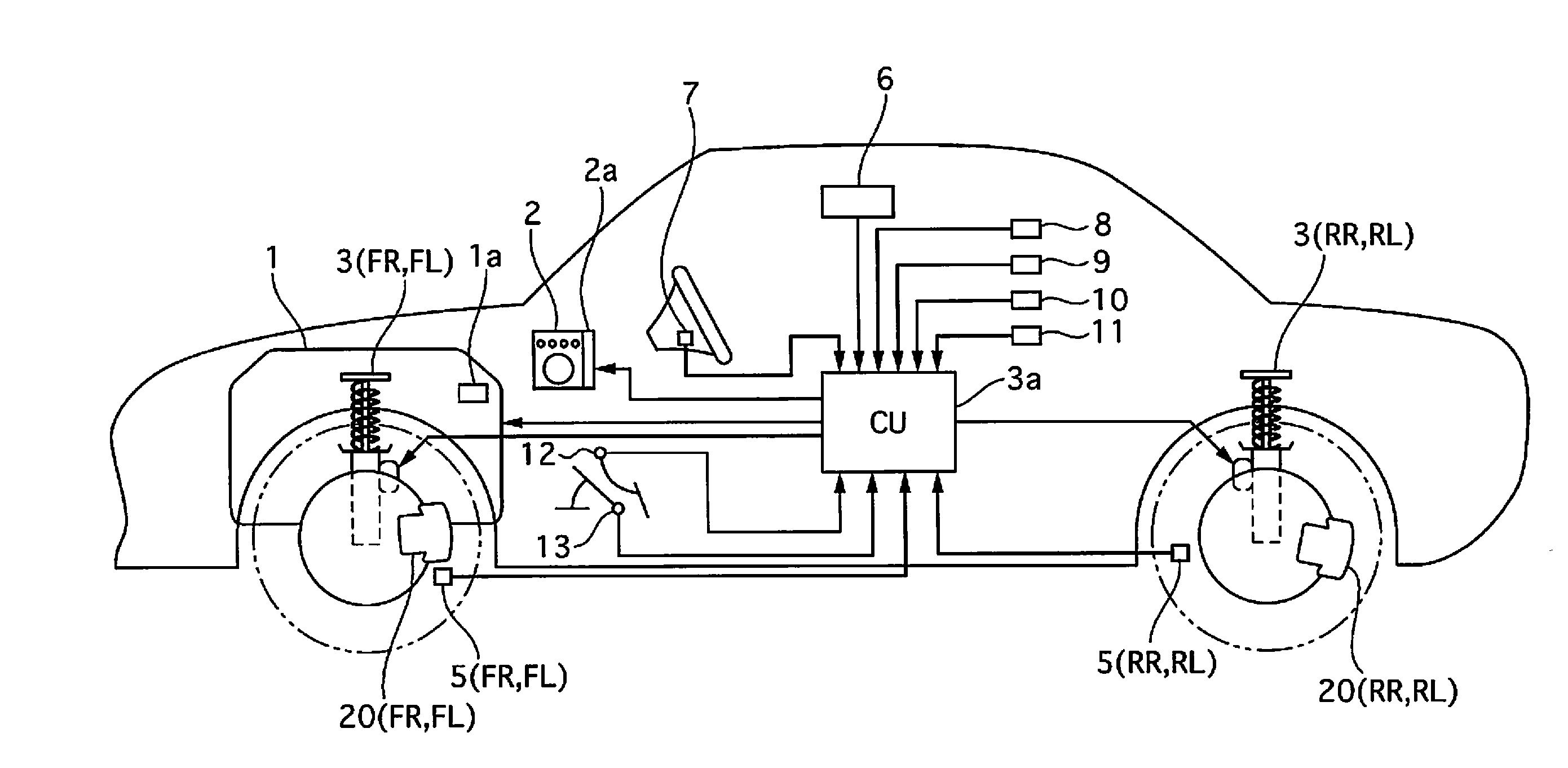
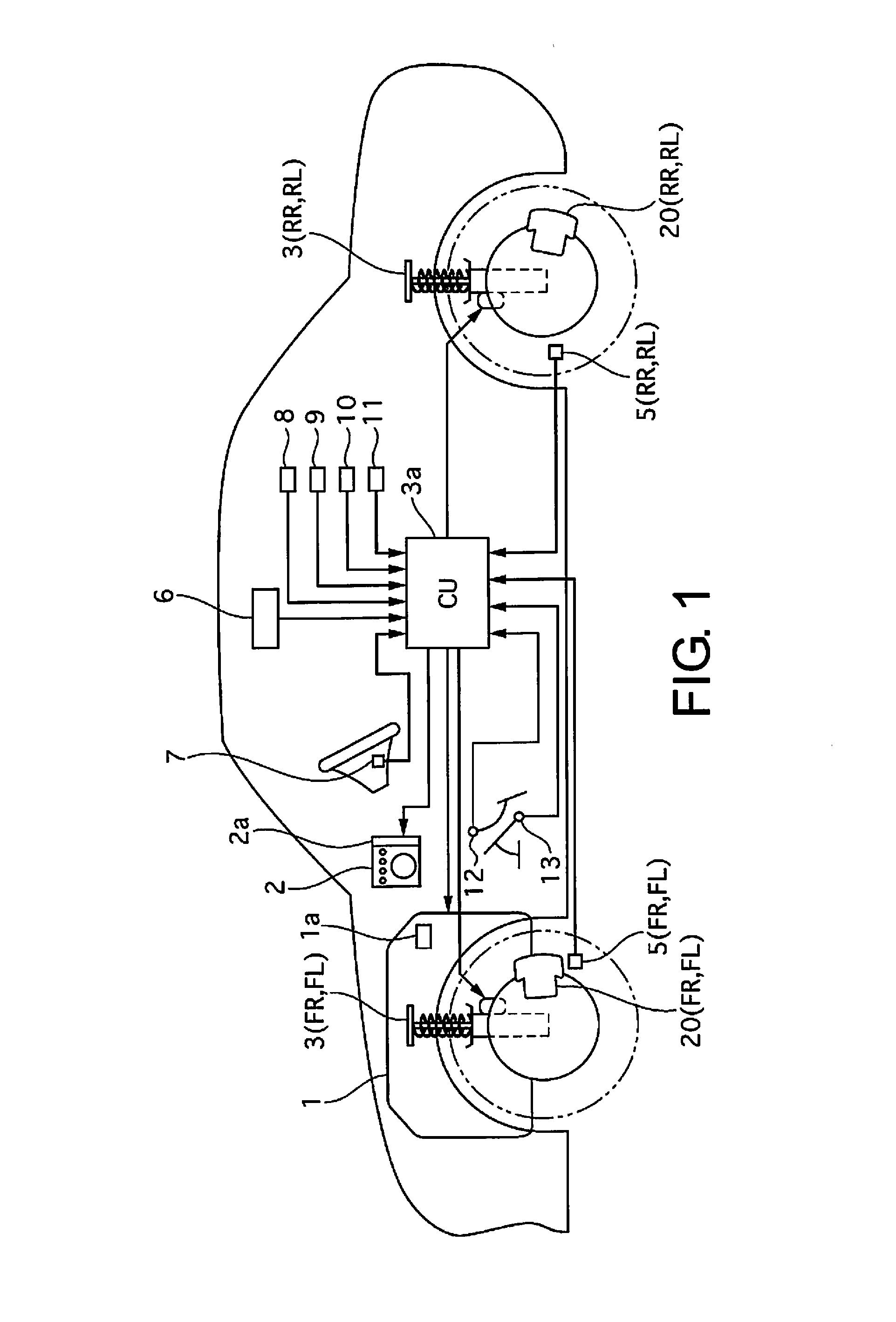
[0035]FIG. 1 is a schematic system diagram showing a vehicle control device according to a first embodiment. A vehicle comprises an engine 1 constituting a power source, brakes 20 for generating braking torque by applying frictional force to the wheels (brakes corresponding to individual wheels will be referred to hereafter as follows: front right brake: 20FR; front left brake: 20FL; rear right brake: 20RR; rear left brake: 20RL), and shock absorbers 3 capable of variable damping force control, provided between each of the wheels and the vehicle body (“shock absorber” will be abbreviated “S / A” in the following description, and S / A corresponding to individual wheels will be referred to as follows: front right S / A: 3FR; front left S / A: 3FL; rear right S / A: 3RR; rear left S / A: 3RL).

[0036]The engine 1 has an engine controller (also referred to hereinafter as an engine control unit, and corresponding to the power source control means) 1a. The engine controller 1a controls the engine oper...


PUM


Abstract

A vehicle control device includes a wheel speed sensor and a controller. The wheel speed sensor detects wheel speed. The controller estimates a sprung mass state based on information in a predetermined frequency region of wheel speed and controls an actuator to bring the estimated sprung mass state to a target sprung mass state. The controller calculates a first wheel speed as a reference wheel speed for individual wheels. The controller calculates a second wheel speed as a reference wheel speed of front and rear wheels. The controller calculates a third wheel speed as a reference wheel speed of all wheels. The controller calculates a reference wheel speed of each wheel. The controller detects that the estimation accuracy has deteriorated when a differential among reference wheel speeds of the wheels is equal to or greater than a prescribed value.

Description

CROSS-REFERENCE TO RELATED APPLICATIONS[0001]This application is a U.S. National stage application of International Application No. PCT / JP2013 / 063241, filed May 13, 2013, which claims priority to Japanese Patent Application No. 2012-110305 filed in Japan on May 14, 2012.BACKGROUND[0002]1. Field of the Invention[0003]The present invention relates to a control device and a control method for controlling the state of a vehicle.[0004]2. Background Information[0005]Japanese Laid-Open Patent Application No. 2009-241813 discloses a technology for estimating stroke speed from fluctuations in wheel speed in a predetermined frequency region, and modifying the damping force of a variable damping force shock absorber in accordance with the stroke speed, to control the sprung behavior.SUMMARY[0006]However, a problem encountered in the aforementioned prior art is that when a disturbance of wheel speed within a predetermined frequency region arises, the accuracy of estimation of the stroke speed i...

Claims


Application Information

Patent Timeline
IPC IPC(8): B60G17/016
CPCB60G17/016B60G17/018B60G17/0182B60G17/0195B60G17/06B60G2400/204B60G2400/41B60T7/12B60T2260/06
Inventor KIKUCHI, HIRONOBU
Owner NISSAN MOTOR CO LTD
Why Eureka
Try Eureka