
Wireless active wheel speed sensor

a technology of active wheel speed sensor and wireless technology, applied in the field of wheel speed sensor systems, can solve the problems of inconvenient positioning of sensor on the vehicle, increased complexity and cost, and increased cost of forward biased wheel speed sensor

Inactive Publication Date: 2008-12-11
KELSEY HAYES CO
View PDF34 Cites 36 Cited by
  • Summary
  • Abstract
  • Description
  • Claims
  • Application Information

AI Technical Summary

Benefits of technology

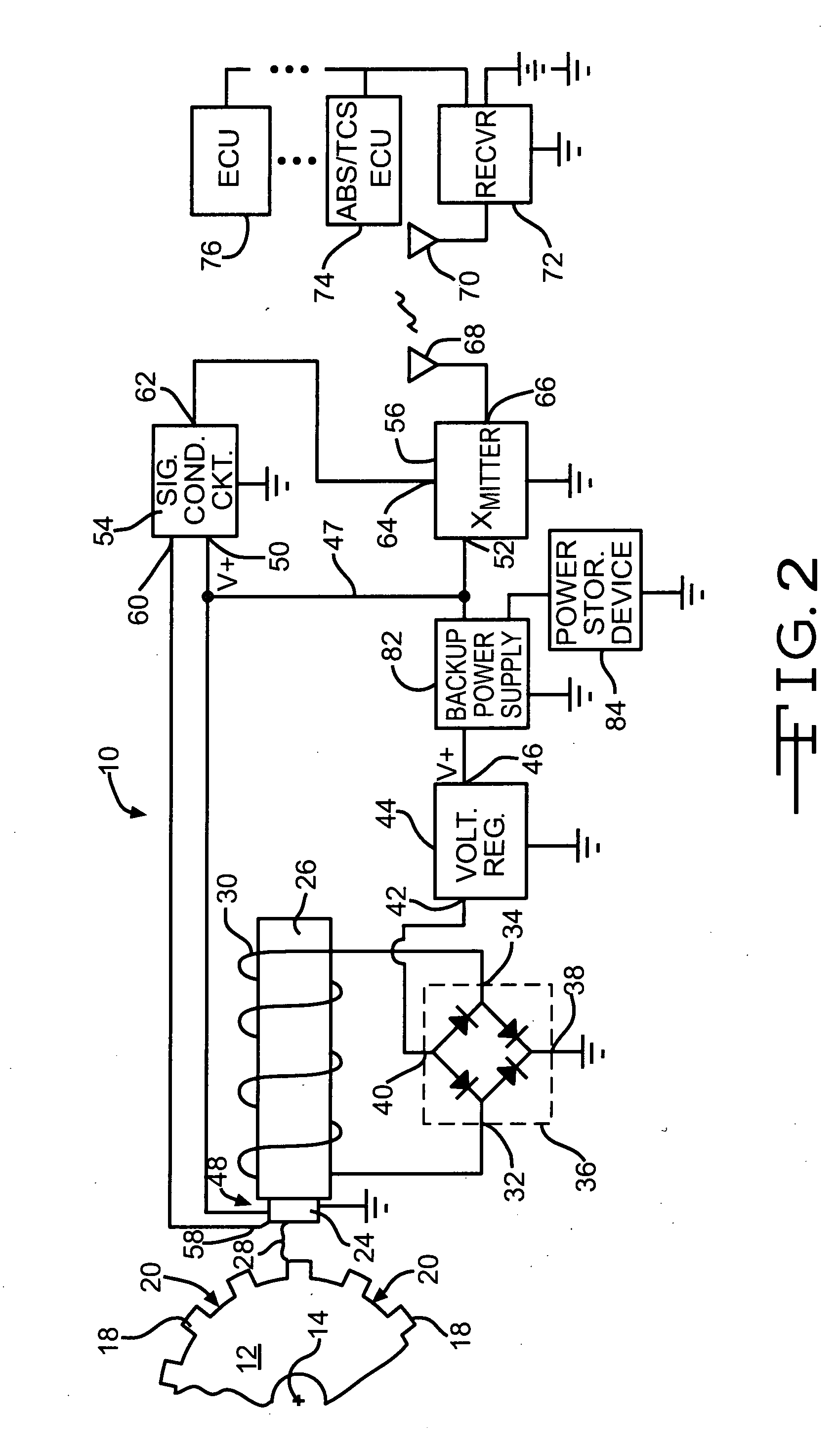
[0009]In another aspect of the present invention, the wireless active rotational speed sensor system may include a rechargeable energy storage device, such as a backup battery or a capacitor, and a control circuit for supplying power to the components of the sensor when the target is not rotating or rotating at an insufficient speed to supply the needed power. The power co...

Problems solved by technology

However, forward biased wheel speed sensors require a more complex, and hence more expensive, target than back-biased wheel speed sensors.
One restriction upon utilization of active wheel speed sensors is the need to hard wire the sensor to a vehicle electrical system in order to provide paths for supplying power to the sensor and to communicate sensor output signals to vehicle control systems.
Such hard wiring not only adds complexity and cost, but also can result in limitations regarding the placement of the sensor upon the vehicle.
Additionally, the wiring is included in the vehicle wheel wells and thus may be exposed to damage from suspension and steering components, road debris and / or corrosion from water and salt thrown up into the wheel well by the vehicle wheel.

Method used


Image

  • Wireless active wheel speed sensor
  • Wireless active wheel speed sensor
  • Wireless active wheel speed sensor

Examples


Embodiment Construction

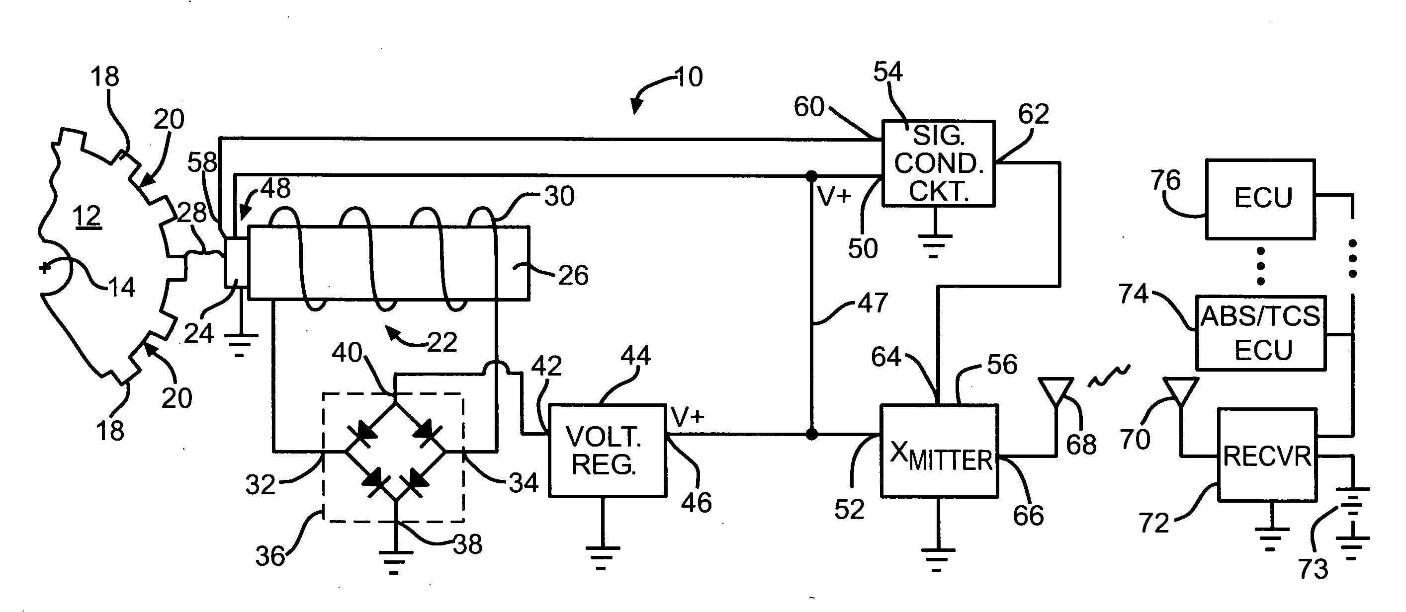
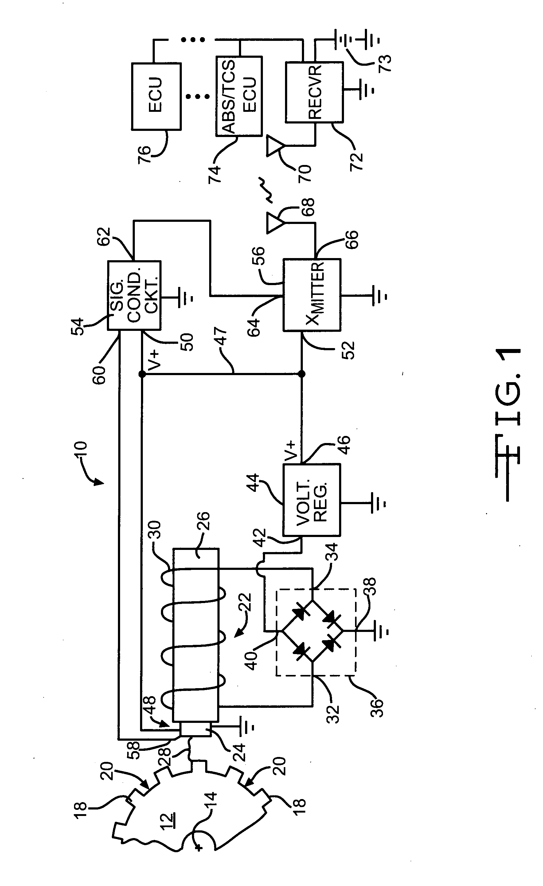
[0014]Referring to FIG. 1, a wireless vehicle wheel speed sensor in accordance with the present invention is shown generally at 10. The wheel speed sensor 10 detects the rotational velocity of a tone wheel 12, also known as an exciter wheel or exciter ring, tone ring, or target, as the tone wheel rotates about an axis 14. The tone wheel 12 is generally circular and includes a plurality of teeth 18 protruding from and spaced equally about its periphery. The individual teeth 18 are separated by spaces 20. The tone wheel 12 is formed from a ferrous material, such as iron or steel or an alloy thereof. The tone wheel 12 is adapted to be mounted upon a rotatable vehicle component (not shown), such as, for example, a vehicle wheel or wheel hub. Thus the tone wheel 12 rotates at the same angular velocity as the vehicle wheel being monitored.

[0015]The wireless wheel speed sensor 10 includes a sensor assembly 22, which includes an active sensing element or device 24 mounted upon one end of to...


PUM


Abstract

A wireless rotational speed sensor system that includes a coil wound around a permanent magnet, the coil co-operating with a rotating ferrous target to induce a voltage for powering an active speed sensor element. The active speed sensor generates an output signal that is a function of the rotational speed of the target. The output signal is supplied to a wireless transmitter and antenna for transmission to other electronic components.

Description

BACKGROUND OF THE INVENTION[0001]This invention relates in general to wheel speed sensors systems and in particular to a wireless active wheel speed sensor.[0002]Vehicle wheel speed sensor systems are well known. Vehicle wheel angular velocity is used for numerous measurement devices and control systems, including but not limited to vehicle speedometer readings, vehicle cruise control, vehicle antilock braking systems, electronic stability programs, telematic systems, and roll stability programs. Speed sensor systems typically operate by means of a target with alternating magnetic poles or alternating ferrous geometry installed on a rotating wheel end component. This target is paired with a stationary sensor mounted to a wheel end static component and is separated from the stationary sensor by an air gap. The stationary sensor generates a signal when the moving target passes over a read component of the sensor. Dependent upon the technology employed, the robustness of the output sig...

Claims


Application Information

Patent Timeline
IPC IPC(8): G01P3/42
CPCG01P3/488
Inventor TURNER, JASON D.
Owner KELSEY HAYES CO
Learn More