

Suspension control apparatus
a technology of suspension control and control apparatus, which is applied in the direction of shock absorbers, instruments, cycle equipment, etc., can solve the problems of increasing the cost of sensors, and achieve the effect of reducing the number of sensors
- Summary
- Abstract
- Description
- Claims
- Application Information
AI Technical Summary
Benefits of technology
Problems solved by technology
Method used
Image

Examples
first embodiment
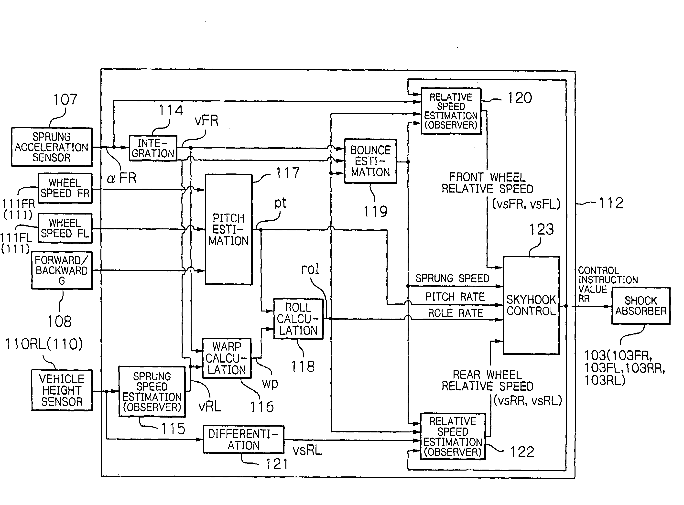
[0034]A suspension control apparatus of a first embodiment comprises a damping force adjustable shock absorber interposed between a vehicle body and a vehicle wheel, and a control apparatus. Damping characteristics of the shock absorber are changed according to an instruction from an outside. The control apparatus is operable to control the damping characteristics of the shock absorber. The control apparatus comprises a first up / down motion calculating unit operable to calculate an up / down motion of a first point set to any position in the vehicle body, a roll motion estimating unit operable to estimate a roll motion of the vehicle body, a pitch motion estimating unit operable to estimate a pitch motion of the vehicle body, a various portions up / down motion calculating unit operable to calculate up / down motions of various portions of the vehicle body from the up / down motion, the roll motion and the pitch motion, and a controller operable to calculate an instruction according to the ...
second embodiment
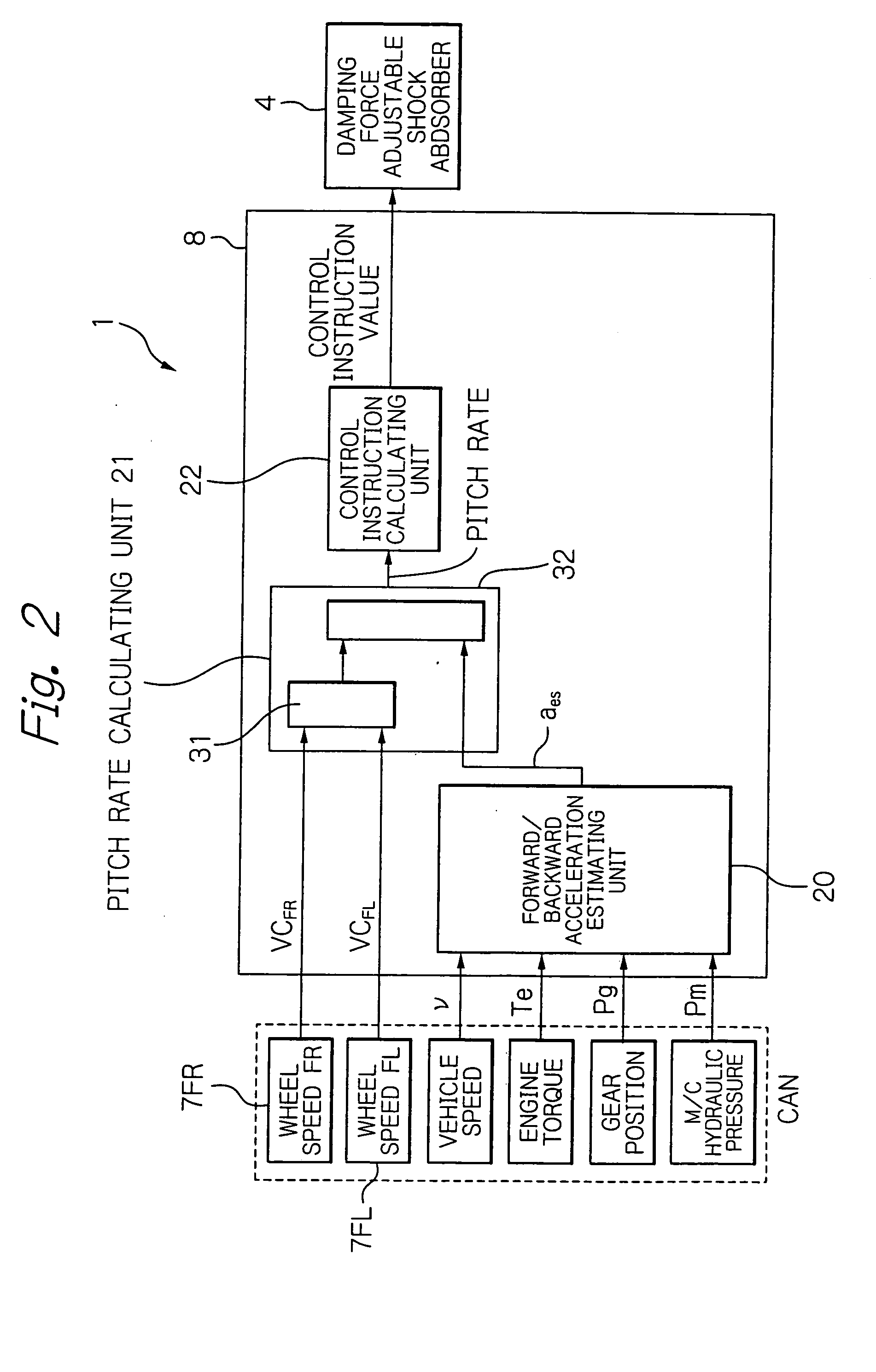
[0136]The control apparatus 8 in the above-mentioned embodiment may be replaced by a control apparatus 8A comprising the pitch rate estimating unit 21 as mentioned above, an up / down acceleration estimating unit (first up / down motion calculating unit) 51 operable to estimate an up / down acceleration of the vehicle body 6, a roll rate calculating unit (roll motion estimating unit) 52 operable to calculate (estimate) a roll rate of the vehicle body 6, an up / down motion calculating unit 53 operable to calculate up / down motions of various portions of the vehicle body 6 from the up / down acceleration, the roll rate and the pitch rate, and a controller 54 operable to send a predetermined instruction based on the calculated up / down motion to the shock absorber 4, as shown in FIG. 7.
[0137]According to the second embodiment, the pitch rate calculating unit 21 calculates a pitch rate with accuracy as in the first embodiment. The up / down motion calculating unit 53 obtains an up / down motion signal...
third embodiment
[0139]The control apparatus 8 may be replaced with a control apparatus 8B comprising, as shown in FIG. 8, a first up / down acceleration calculating unit 61 operable to calculate an up / down acceleration at a first point of the vehicle body 6 and a second up / down acceleration calculating unit 62 operable to calculate an up / down acceleration at a second point of the vehicle body 6, instead of the up / down acceleration estimating unit 51 and the roll rate calculating unit 52 in the second embodiment which roll rate calculating unit 52 calculates (estimates) the roll rate of the vehicle body 6. As shown in FIG. 8, the control apparatus 8B further comprises an up / down motion calculating unit 53A operable to calculate up / down motions of various portions of the vehicle body 6 based on the up / down accelerations of the first and second points and the pitch rate, instead of the up / down motion calculating unit 53 which calculates the up / down motions of the various portions of the vehicle body 6 b...
PUM
 Abstract
Description
Claims
Application Information