Cooler door shelf device with flexible display

a door shelf and flexible technology, applied in the field of coolers, can solve the problems of inability to change the advertising on the support panel, small areas lack the impact needed, etc., and achieve the effect of improving air circulation and increasing air flow

Inactive Publication Date: 2007-12-11
DISPLAY INDS
View PDF21 Cites 16 Cited by
  • Summary
  • Abstract
  • Description
  • Claims
  • Application Information

AI Technical Summary

Benefits of technology

[0006]The shelf device utilizes space in the cooler that would otherwise be wasted. The shelf device increases visual appeal and places product identification at the door where it is more readily seen than that on the containers further back in the cooler. The display panel insert is slidably received by the slots in the ribs with ends of the insert disposed in the recesses of the flanges. Because the shelf device is supported via openings in the flanges above and below the display panel and is spaced from the door by suction cups, the insert can be inserted and removed while the shelf device is mounted on the cooler door. The recesses allow the display panel to be inserted and removed but retains the insert against inadvertent removal.
[0008]The slots and recesses allow the display panel insert to fit flush with the mounting flanges. Positioning the display panel above the bottom panel creates a space for improved air circulation. Ventilation openings also promote increased air flow.

Problems solved by technology

Door shelving fits against the door so that the product containers are visible, however the product labels do not always face forward for easy identification of the product.
Some shelves have a small area for affixing product identification, but such small areas lack the impact needed, especially for impulse purchases.
Advertising on the support panel cannot be changed while the shelf is attached to the cooler door because the lower openings and suction cups block access.

Method used


Image

  • Cooler door shelf device with flexible display
  • Cooler door shelf device with flexible display
  • Cooler door shelf device with flexible display

Examples


Embodiment Construction

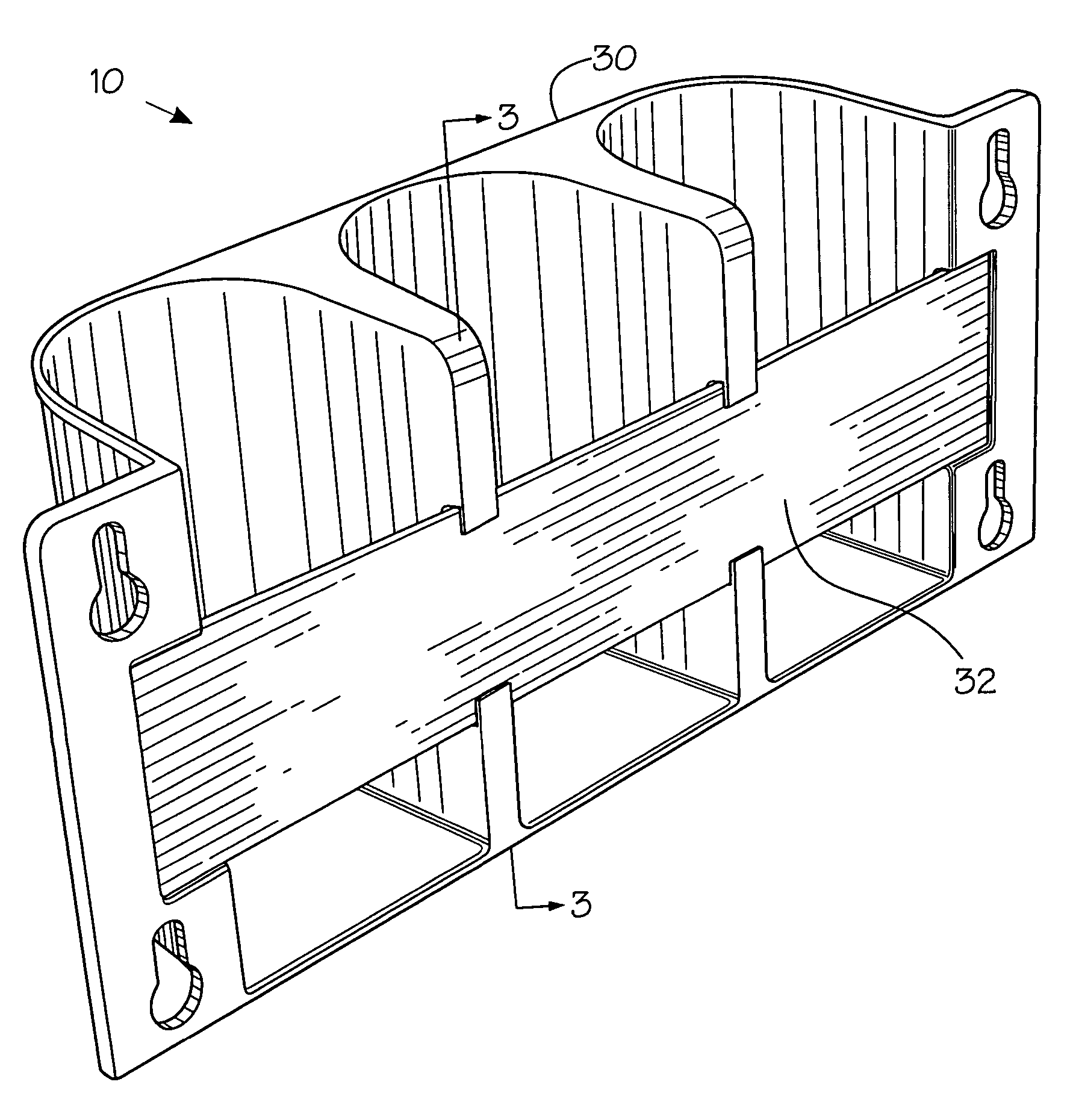
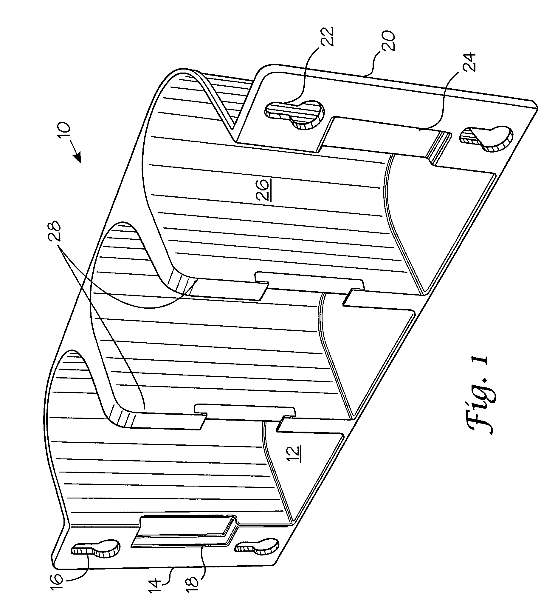
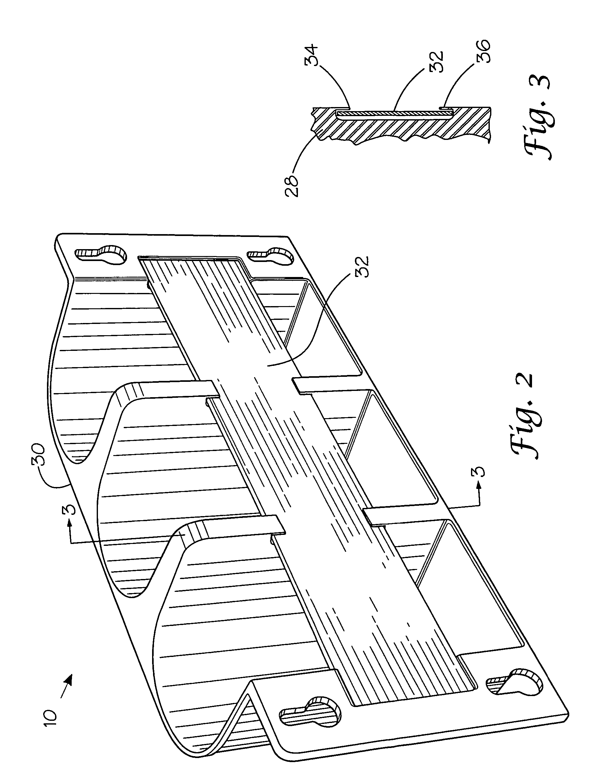
[0013]Referring to FIGS. 1-3, a shelf device 10 is provided for attaching to an inside surface of an upright cooler door. Articles, such as beverage containers for example, can be placed on shelf device 10 for easy viewing through the cooler door which minimizes the need to open the door to view the contents. It also utilizes the door space for storing additional product in a space that may otherwise be wasted. Product on the shelf device always remains up front within the easy view and grasp of a consumer.

[0014]Shelf device 10 has a bottom panel 12 with front, rear, left and right side edge portions. A left mounting flange 14 is connected to bottom panel 12 along the front and left side edge portions and extends upward therefrom. Upstanding left mounting flange 14 preferably has a pair of slotted openings or keyways 16 therein vertically spaced from one another and adapted to mount and support the shelf device in conjunction with suction cups or the like. Left flange 14 has a slot ...


PUM


Abstract

A shelf device for mounting on an inside surface of a cooler door comprises a bottom panel and left and right mounting flanges connected to the bottom panel along left and right side edge portions thereof. Each flange has a pair of openings therein vertically spaced from one another and adapted to mount and support the shelf device. A partition panel is connected to the bottom panel and divides the bottom panel into a plurality of compartments. Vertically extending ribs are attached to the partition panel at junctions of adjacent compartments. A display panel insert is received by slots in the ribs and recesses in the mounting flanges.

Description

CROSS REFERENCE TO RELATED APPLICATIONS[0001]This application is a continuation in part of application Ser. No. 10 / 990,815 filed Nov. 17, 2004, entitled “cooler Door Shelf Device” and is related to commonly assigned co-pending application Ser. No. 10 / 929,975 filed Aug. 20, 2004 entitled “Cooler Door Shelf Device With Removable Product Panel”; Ser. No. 10 / 944,246, filed Sep. 16, 2004 entitled “Cooler Door Shelf Device With Stick-On Display Panels”; Ser. No. 10 / 944,295, filed Sep. 16, 2004 entitled “Cooler Door Shelf Device With Raised Panels”; Ser. No. 10 / 947,467, filed Sep. 22, 2004, entitled “Neck-Hanging Cooler Door Shelf Device”; and Ser. No. 10 / 947,472, filed Sep. 22, 2004, entitled “Vented Cooler Door Shelf Device”.TECHNICAL FIELD OF THE INVENTION[0002]This invention relates generally to a cooler, and, more particularly, to a door shelf device for a transparent cooler door.BACKGROUND OF THE INVENTION[0003]Upright coolers in supermarkets and convenience stores typically have tra...

Claims


Application Information

Patent Timeline
Patent Type & Authority Patents(United States)
IPC IPC(8): A47B73/00
CPCA47B96/02F25D23/04F25D2331/805
Inventor ROBERTSON, JAMES DAVID
Owner DISPLAY INDS
Why Eureka
Try Eureka