Table device

Inactive Publication Date: 2007-12-11
NSK LTD
View PDF17 Cites 3 Cited by
  • Summary
  • Abstract
  • Description
  • Claims
  • Application Information

AI Technical Summary

Benefits of technology

[0016]The channel is formed in communication from the gap of a gas reservoir formed between the joining member and the receiving portion to the outside of the table apparatus. The air in the gas reservoir is easily discharged through the channel to the outside of the table apparatus.
[0020]The air in the gap which forms the gas reservoir between the joining member and the receiving portion is easily discharged to the outside of the table apparatus through the perforated gas vent hole. The gas vent hole is preferably perforated through the member constituting the table apparatus so as to be substantially in perpendicular to the direction along which the receiving portion is formed. Alternatively, the gas vent hole is preferably perforated through the member that constitutes the table apparatus in substantially axial direction along which the receiving portion is formed.
[0022]The gap forming the gas reservoir between the joining member and the receiving portion is in communication with the outside of the table through the groove, and the air in the gas reservoir is easily discharged to the outside of the table apparatus.
[0026]Even though the end of the groove is closed, the groove is in communication with the outside of the table apparatus through the communication channel. Accordingly, the air in the gap which forms the gas reservoir between the attaching screw hole and the attaching screw is easily discharged through the groove and the communication channel to the outside of the table apparatus.
[0029]The washer situates below the head of the attaching screw and the attaching screw is screwed in the attaching screw hole. Accordingly, the washer closes a portion above the gap which forms the gas reservoir between the attaching screw hole and the attaching screw and, further, the head of the attaching screw covers a portion above the washer. Then, since the washer has the channel connecting from the gas reservoir to the outside of the table apparatus, the air in the gas reservoir is easily discharged to the outside of the table apparatus through the channel of the washer.

Problems solved by technology

It takes much time, particularly, in a case where the extent of the outside vacuum condition is high.
The gas reservoir causing such a problem is present on every portions where members constituting the table apparatus with the linear guide device are joined to each other by combination of screws and screw holes.
However, the special screws are expensive and it is not easy to fabricate vent holes to screws of various sizes used for assembling and combining the members that constitute the table apparatus.

Method used


Image

  • Table device
  • Table device
  • Table device

Examples


first embodiment

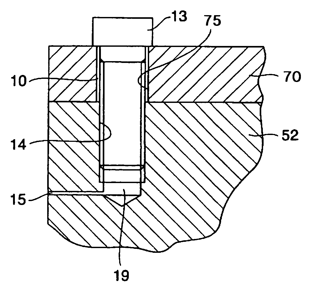
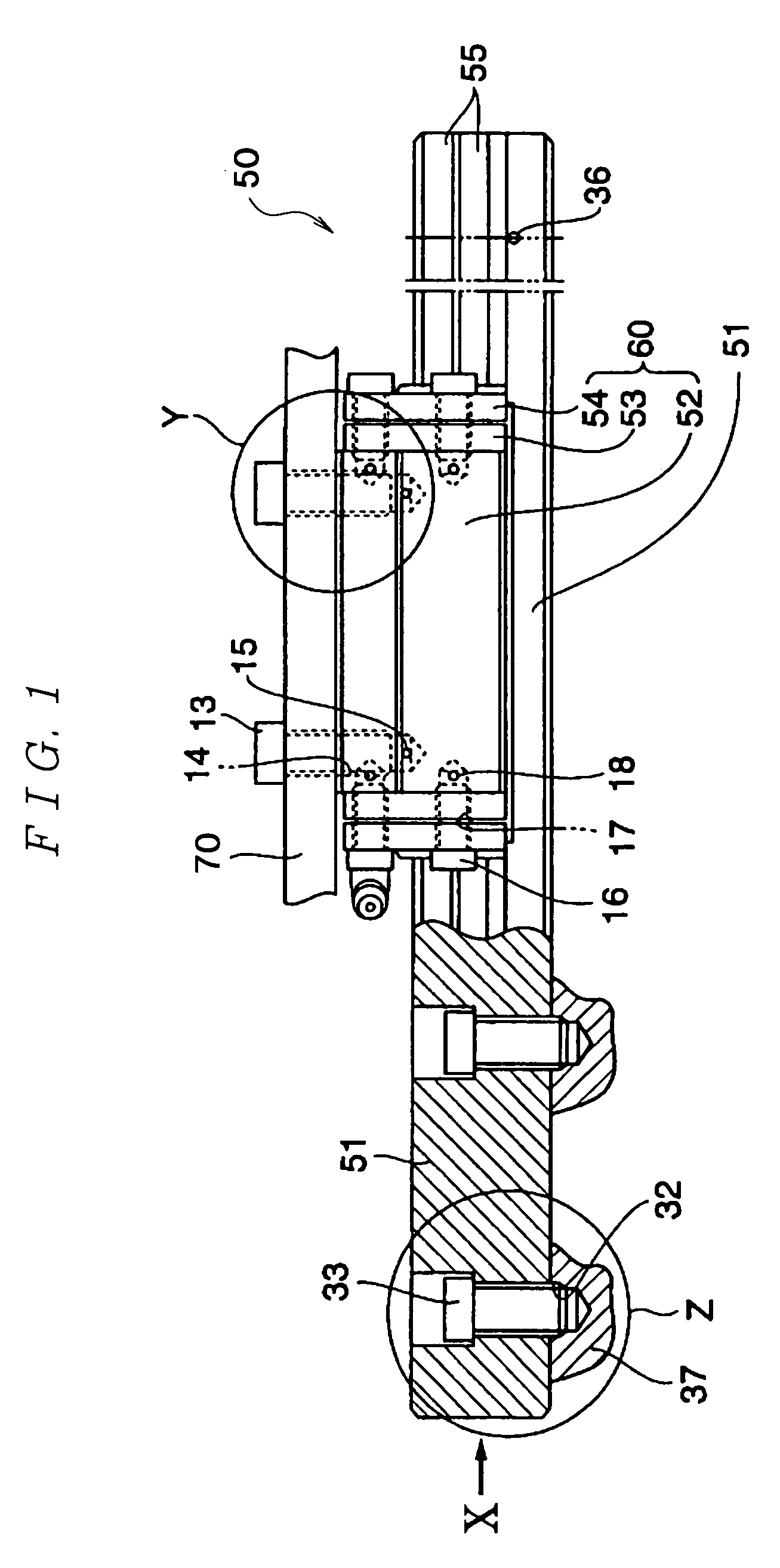
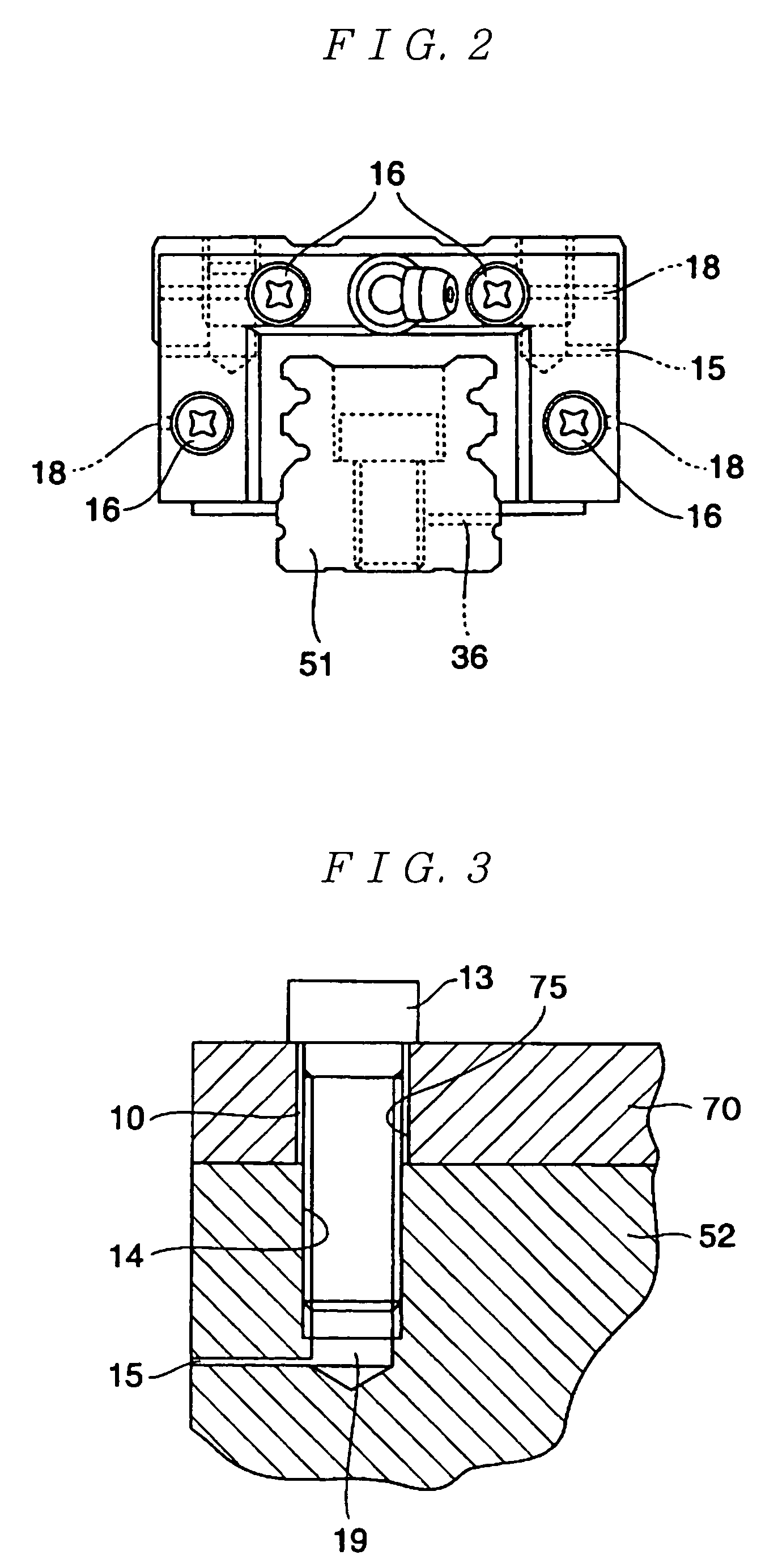
[0059]the present invention is to be described with reference to FIG. 1 to FIG. 4.

[0060]FIG. 1 is a front elevational view showing a table apparatus comprising a linear guide device having a guide rail 51 and a slider 60, a slider-side member 70 attached to the linear guide device and a substructure 37 as a guide rail-side member to which the linear guide device is attached, which is partly shown as a cross sectional view and also partly shown as a perspective view. FIG. 2 is a side elevational view of the linear guide device having the guide rail 51 and the slider 60 of the FIG. 1 as viewed along the direction X. FIG. 3 is an enlarged view of portion Y in FIG. 1 viewed from the right side and FIG. 4 is an enlarged view showing portion Z in FIG. 1 viewed from the right side.

[0061]As shown in FIG. 1, the table apparatus according to this embodiment comprises a linear guide device 50 having the guide rail 51 and the slider 60, the slider-side member 70 and the substructure 37 as the g...


PUM


Abstract

A table apparatus with a linear guide device according to the present invention comprises a plurality of members constituting the linear guide device, other members to which the linear guide device is attached and screws for joining a predetermined combination of the members with each other, and screw holes for receiving the screws are formed to the members comprising the combination, and a gas vent hole in communication with a gap formed between the screw and the screw hole by receiving the screw in the screw hole, and the gas vent hole is perforated through the member constituting the table apparatus. When the table apparatus is put under evacuated or depressurized circumstances, remaining air in the gap formed between the screw and the screw hole can be discharged through the gas vent hole in a short period of time, a table apparatus suitable to be used under evacuated or depressurized circumstances can be provided.

Description

TECHNICAL FIELD[0001]This invention relates to a linear guide device and a table apparatus with the linear guide device and, more in particular, it relates to a linear guide device having a structure suitable to be used in vacuum or depressurized circumstances, as well as a table apparatus with the linear guide device.BACKGROUND ART[0002]FIG. 26 shows a perspective view of an existent linear guide device. The linear guide device comprises a guide rail 51 and a slider 60. The slider 60 comprises a slider main body 52, end caps 53 and side seals 54. Then, the linear guide device, a not illustrated guide rail-side member and a not illustrated slider-side member constitute a table apparatus. The not illustrate guide rail-side member is, for example, a substructure to which the guide rail is secured and the not illustrated slider-side member is, for example, a table secured to the slider main body.[0003]The guide rail 51 is extended in one direction and has rolling element grooves 55 on ...

Claims


Application Information

Patent Timeline
IPC IPC(8): F16C29/06B23Q1/00B23Q1/58F16C29/00
CPCB23Q1/0018B23Q1/58F16C29/0638F16C29/005F16C29/004F16C2322/39
Inventor NAKAMURA, TSUYOSHISAJI, NOBUHITOTAJIMI, HIDEYUKI
Owner NSK LTD
Why Eureka
Try Eureka