Liquid ejecting head and liquid ejecting apparatus having same

Active Publication Date: 2009-08-06
SEIKO EPSON CORP
View PDF1 Cites 3 Cited by
  • Summary
  • Abstract
  • Description
  • Claims
  • Application Information

AI Technical Summary

Benefits of technology

[0011]An advantage of some aspects of the invention is a liquid ejecting head capable of easily discharging air bubbles while preventing minute through-holes from being blocked by adhesive, and an accompanying liquid ejecting apparatus.
[0013]According to the above configuration, the affinity for the adhesive of the inner peripheral surface of the second through-hole is set to be higher than the affinity for the adhesive of an area around the opening of the first through-hole, such that adhesive that flows out from between the first plate and the second plate at the time of bonding is guided to the inner peripheral surface of the second through-hole. Thus, the adhesive can be prevented from forming a recess in the inner peripheral surface of the passage between the first plate and the second plate. In addition, the adhesive can be prevented from flowing toward the first through-hole, which has a smaller diameter. As a result, the adhesive can be prevented from blocking the first through-hole, and the ease of discharging air bubbles can be improved.

Problems solved by technology

It is difficult to completely prevent this.
If such air bubbles stay in the ink passages, the air bubbles can absorb the pressure fluctuation at the time of the ejecting operation, causing a pressure loss.
In addition, the air bubbles can block the passages, thereby causing an inadequate supply of ink to the recording head.
Once air bubbles B enter this recess, it is difficult to remove the air bubbles, even when a cleaning operation is performed, so the above-described problems cannot be fixed.

Method used


Image

  • Liquid ejecting head and liquid ejecting apparatus having same
  • Liquid ejecting head and liquid ejecting apparatus having same
  • Liquid ejecting head and liquid ejecting apparatus having same

Examples


Embodiment Construction

[0022]The exemplary embodiments of the invention will now be described with reference to the drawings. In the following embodiments, various limitations are described as the preferred embodiments of the invention. However, the scope of the invention is not limited to these embodiments unless specifically specified in the following description.

[0023]In the following description, the liquid ejecting head is described using an ink jet recording head, hereinafter referred to as a recording head, mounted in an ink jet recording apparatus, as an example of a recording head and apparatus capable of performing aspects of the invention.

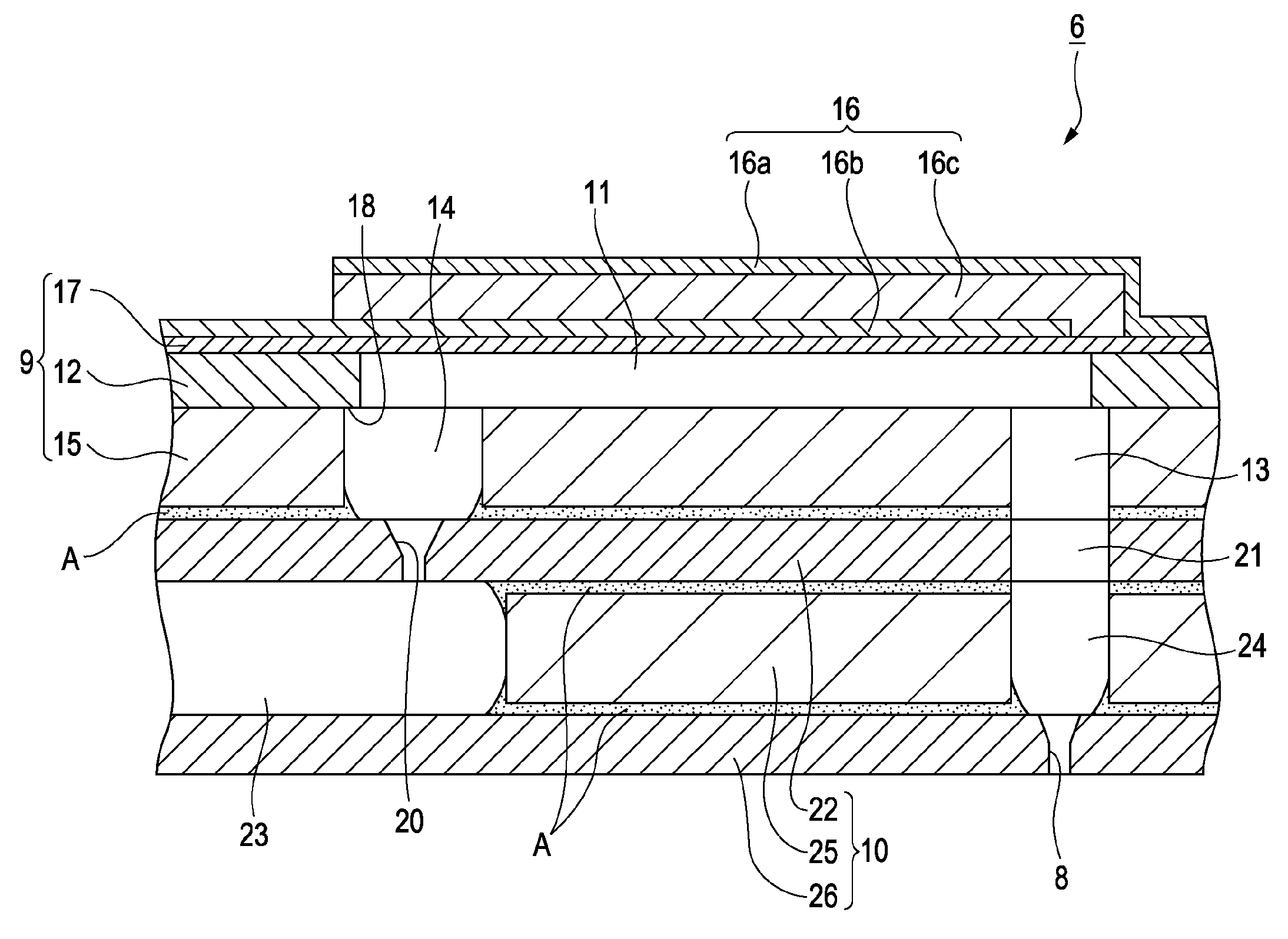
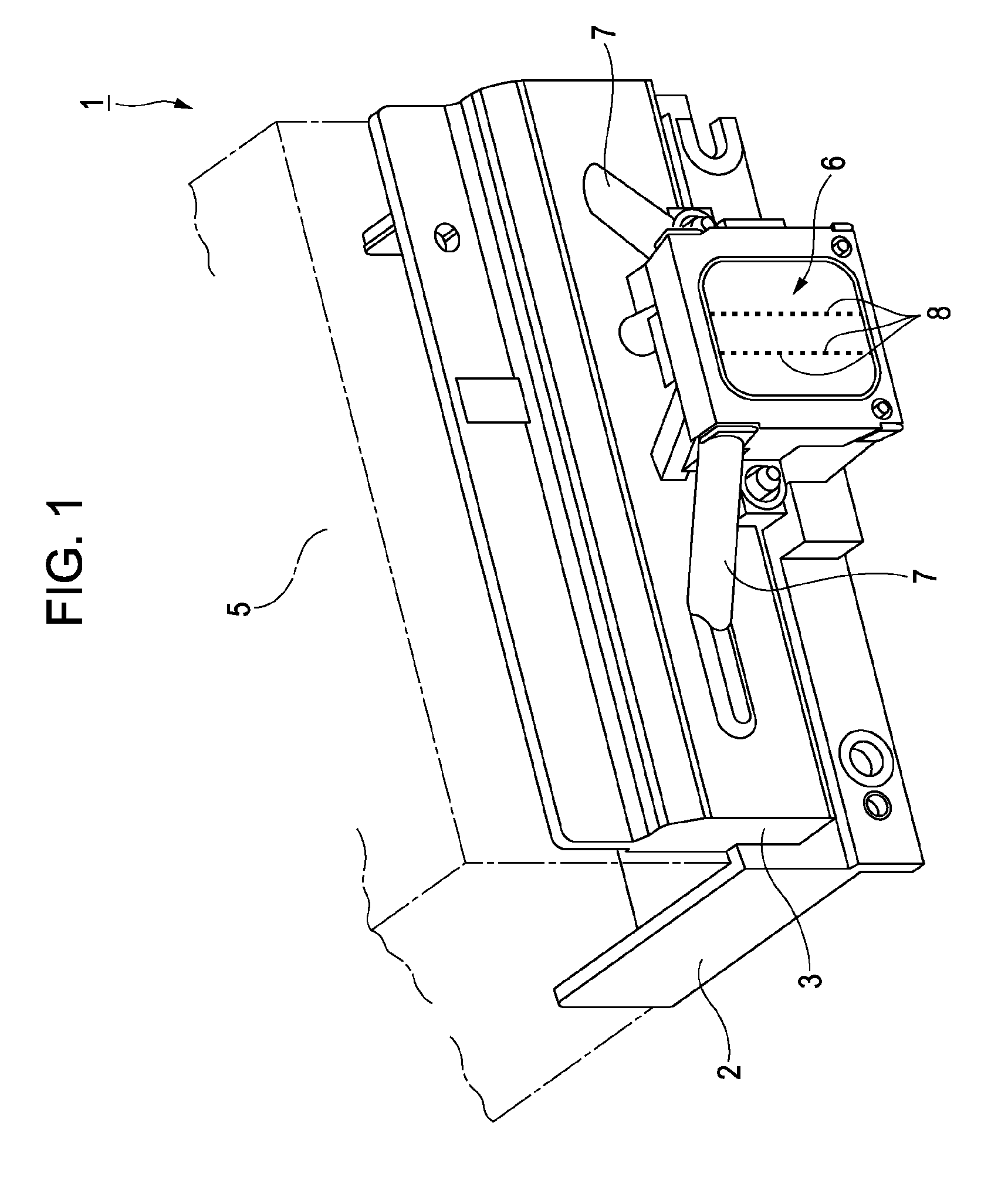
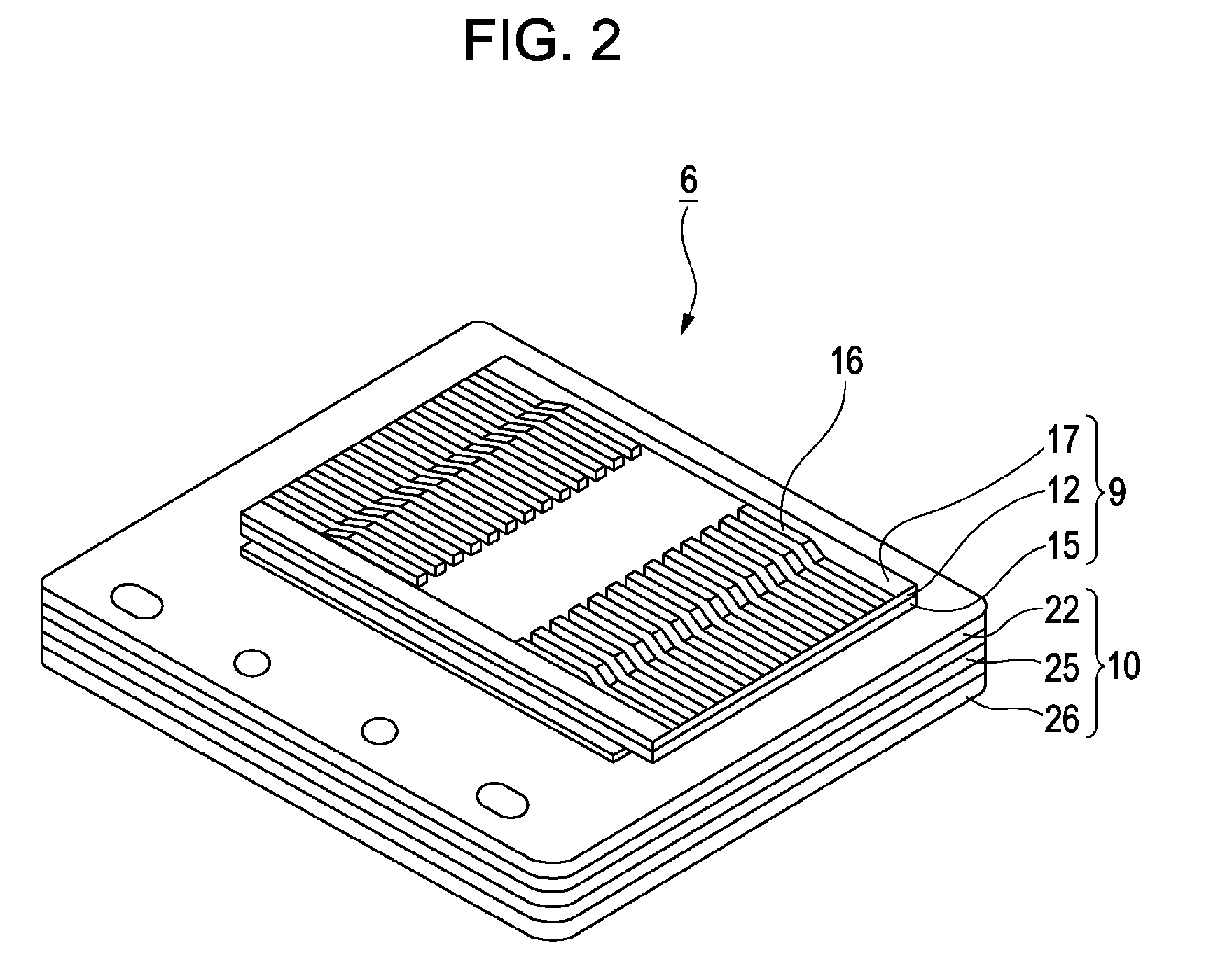
[0024]FIG. 1 is a perspective view of a head unit 1 having a recording head 6 as viewed from the side of the nozzle plate of the recording head 6. FIG. 2 is a perspective view of the recording head 6 as viewed from the side of the piezoelectric vibrator. FIG. 3 is a sectional view of a component of the recording head 6.

[0025]As shown in FIG. 1, the head unit 1...


PUM


Abstract

A liquid ejecting head includes a passage unit made by laminating a plurality of plates including a first plate having a first through-hole with a first size and a second plate having a second through-hole with a second size which is larger than the first size. The first plate and the second plate are bonded with adhesive so that the first through-hole and the second through-hole in communication with each other. The affinity for the adhesive to bond to the inner peripheral surface of the second through-hole is set to be at least higher than the affinity for the adhesive to bond to the area around the opening of the first through-hole. Adhesive that flows out from between the first plate and the second plate at the time of bonding of the first plate and the second plate is guided to the inner peripheral surface of the second through-hole.

Description

BACKGROUND OF THE INVENTION[0001]The entire disclosures of Japanese Patent Application Nos. 2008-020356, filed Jan. 31, 2008, 2008-116677, filed Apr. 28, 2008, are expressly incorporated herein by reference.[0002]1. Technical Field[0003]The present invention relates to a liquid ejecting head, such as an ink jet recording head, and a liquid ejecting apparatus. More specifically, the present invention relates to a liquid ejecting head having an improved ability to discharge air bubbles in the liquid ejecting head, and a liquid ejecting apparatus having the same.[0004]2. Related Art[0005]Examples of liquid ejecting heads currently known in the art that eject or discharge liquid from a nozzle orifice by fluctuating the pressure of the liquid in a pressure chamber include, for example, an ink jet recording head (hereinafter referred to as a recording head) used in an image recording apparatus such as an ink jet recording apparatus (hereinafter referred to as printer), a color material ej...

Claims


Application Information

Patent Timeline
IPC IPC(8): B41J2/16
CPCB41J2/14233B41J2/1623B41J2/161
Inventor HIRASAWA, YUSUKEUEZAWA, HARUHISA
Owner SEIKO EPSON CORP
Why Eureka
Try Eureka