Noise suppressing method and apparatus thereof

a technology of optical noise and noise suppression, applied in the field of optical transmission systems, can solve the problems of forced interference between the noise lights of the first and second components, and achieve the effects of reducing the influence of polarization fluctuation, maximizing the osnr of the combined light, and reducing the interference between the noise components at the combination

Inactive Publication Date: 2007-12-11
KDDI CORP
View PDF2 Cites 4 Cited by
  • Summary
  • Abstract
  • Description
  • Claims
  • Application Information

AI Technical Summary

Benefits of technology

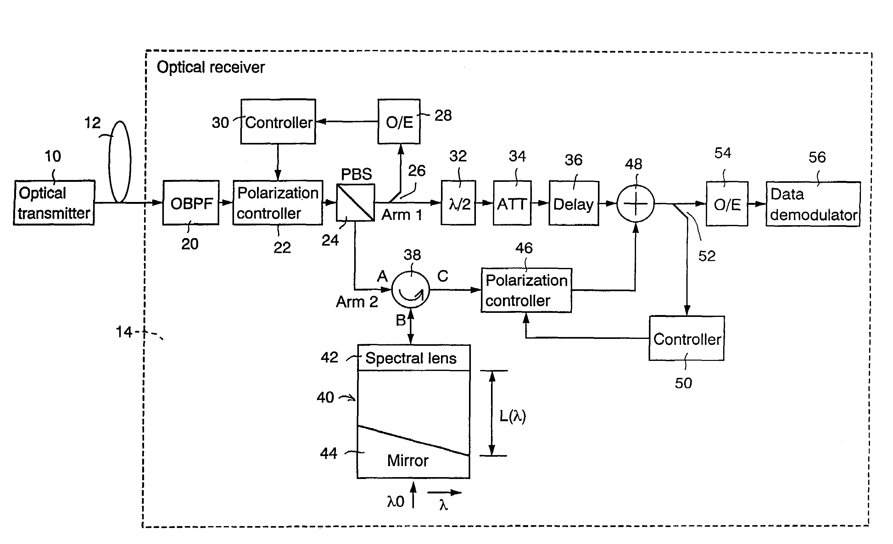
[0008]By using a spectral delay which has a delay amount to differ according to a wavelength in order to shift the optical phase of the second component, it is possible to shift the optical phase of a noise component by a desired amount in each wavelength within the signal band. This makes the interference between the noise components at the combination more effectively.
[0009]In addition, preferably, the polarization of the second component in the second arm is adjusted to maximize an OSNR of the combined light. With this operation, it is possible to reduce the influence from the polarization fluctuation of the second component in the second arm. More specifically, the polarization of the second component in the second arm is adjusted to minimize the intensity of the component with the polarization orthogonal to the polarization direction of the signal light included in the combined light. Alternatively, the polarization direction of the second component in the second arm is adjusted to maximize a degree of polarization of the combined light.
[0010]Furthermore, preferably, the combined light is divided into a third component with the polarization parallel to the polarization direction of the signal light included in the combined light and a fourth component the polarization orthogonal to the polarization direction of the third component, the polarization of the first component in the first arm is adjusted to maximize the intensity of a base repetition frequency component of the signal obtained from the third component, and the polarization of the second component in the second arm is adjusted to minimize the intensity of a low frequency component obtained from the fourth component. With this operation, the influence from the polarization fluctuation in the first and second arms can be reduced.

Problems solved by technology

While the combining is performed, the noise lights included in the first and second components are forced to interfere with each other.

Method used


Image

  • Noise suppressing method and apparatus thereof
  • Noise suppressing method and apparatus thereof
  • Noise suppressing method and apparatus thereof

Examples


Embodiment Construction

[0021]Explanatory embodiments of the invention are explained below in detail with reference to the drawings.

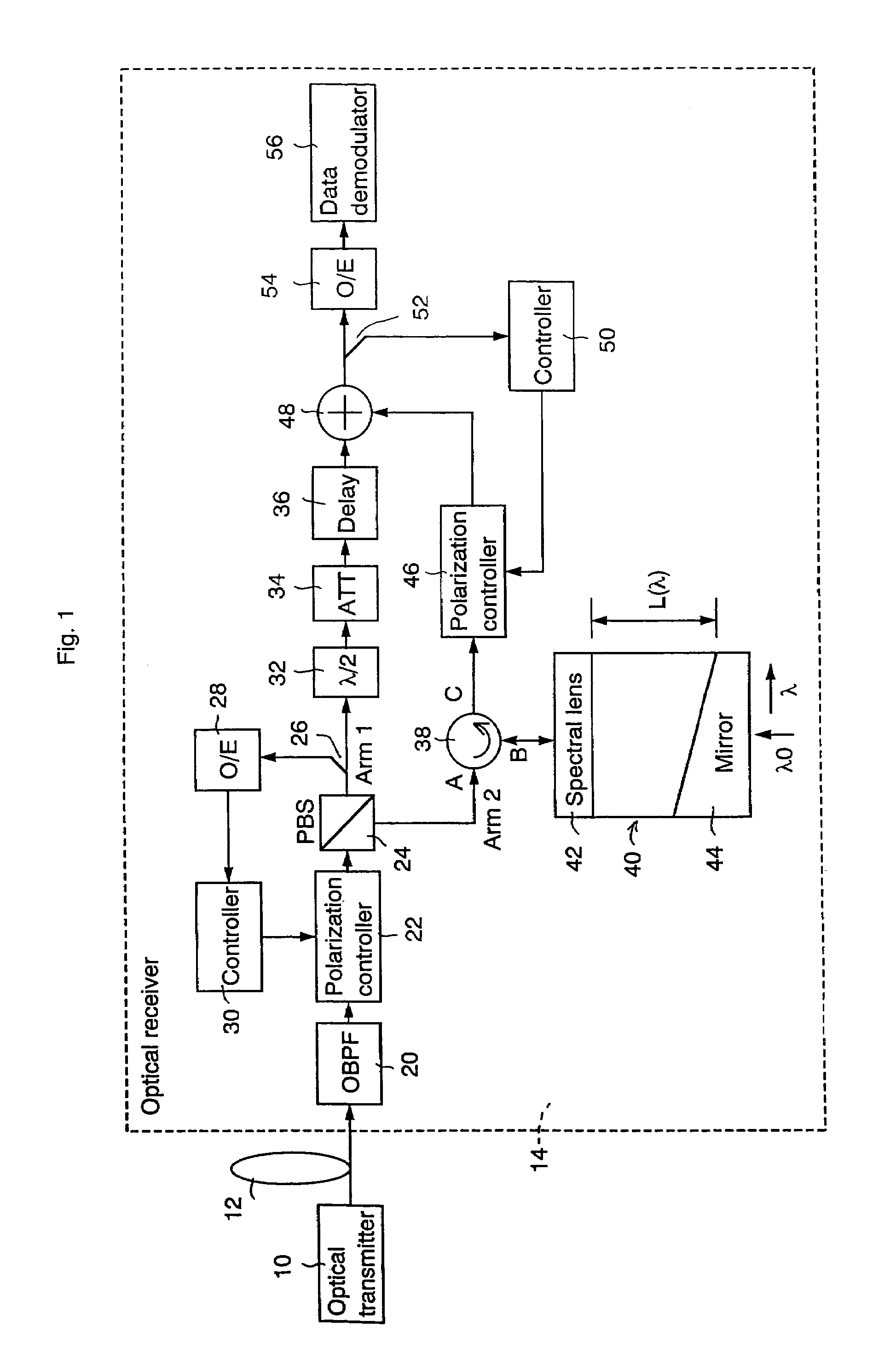
[0022]FIG. 1 shows a schematic block diagram of an explanatory embodiment according to one embodiment of the invention. An optical transmitter 10 outputs a signal light of linear polarization into an optical fiber transmission line 12. The optical fiber transmission line 12 typically comprises an optical repeater amplifier transmission line including one or more optical amplifiers. The signal light propagated in the optical fiber transmission line 12 enters an optical receiver 14. To make it more easily understandable, the receiving configuration of a single wavelength is illustrated as the optical receiver 14.

[0023]The configuration and operation of the optical receiver 14 is explained below. An optical bandpass filter (OBPF) 20 extracts a component of signal wavelength band out of the input light from the optical fiber transmission line 12. The output light from the OBPF 20 ...


PUM


Abstract

In the invention, an input light including a signal light and a noise light within a signal wavelength band of the signal light is divided into a first component with a polarization parallel to a polarization direction of the signal light and a second component with a polarization orthogonal to the polarization direction of the first component. The first component is supplied into a first arm and the second component into a second arm. The optical phase of the second component in the second arm is shifted so that the optical phase of the second component in the second arm relatively differs by π from the optical phase of the first component in the first arm. The first component output from the first arm and the second component output from the second arm are combined to make the noise lights included in the first and second components interfere with each other.

Description

CROSS REFERENCE TO RELATED APPLICATIONS[0001]This application claims priority to Japanese Patent Application No. 2003-145727, filed May 23, 2003, the entire contents of which are incorporated herein by reference.FIELD OF THE INVENTION[0002]This invention relates to a method and apparatus to suppress optical noise components within a signal band.BACKGROUND OF THE INVENTION[0003]In an optical transmission system, specifically in an optical amplifier transmission system, amplified spontaneous emission (ASE) noises are accumulated due to the optical amplification in the course of optical transmission. The ASE noises within a band different from the signal wavelength band are easily removed by a band limited optical filter. However, this type of band limited optical filter is incapable of removing the ASE noises being superimposed on the signal wavelength band.[0004]An ASE noise accumulated within a signal band deteriorates an optical signal to noise ratio, i.e. OSNR, of a signal light. ...

Claims


Application Information

Patent Timeline
Patent Type & Authority Patents(United States)
IPC IPC(8): H04B10/00H04B10/2507H04B10/07
CPCH04B10/674
Inventor HAYASHI, MICHIAKITANAKA, HIDEAKI
Owner KDDI CORP
Why Eureka
Try Eureka