Al technical title is built by PatSnap Al team. It summarizes the technical point description of the patent document.
a scanning region and region technology, applied in the field of scanning light beam displays and imaging devices, can solve the problems of large power consumption, device limitations, and bulky crts, and is undesirable for portable or head-mounted applications
Inactive Publication Date: 2007-12-18
MICROVISION
View PDF4 Cites 22 Cited by
Summary
Abstract
Description
Claims
Application Information
AI Technical Summary
This helps you quickly interpret patents by identifying the three key elements:
Problems solved by technology
Method used
Benefits of technology
Benefits of technology
[0023]In one embodiment of the alternate feeding approach, a single light emitter feeds an input fiber that is selectively coupled to one of two separate fibers by an optical switch. During forward sweeps, the optical switch couples the input fiber to a first of the separate fibers so that the first separate fiber forms the first optical source. During reverse sweep, the optical switch feeds the second separate fiber so that the second separate fiber forms the second source. This embodiment thus allows a single light emitter to provide light for both optical sources.
Problems solved by technology
Such devices suffer from several limitations.
For example, CRTs are bulky and consume substantial amounts of power, making them undesirable for portable or head-mounted applications.
Such screens have limited use in head mounted applications or in applications where the display is intended to occupy only a small portion of a user's field of view.
Such displays have been reduced in size, at the cost of increasingly difficult processing and limited resolution or brightness.
Also, improving resolution of such displays typically requires a significant increase in complexity.
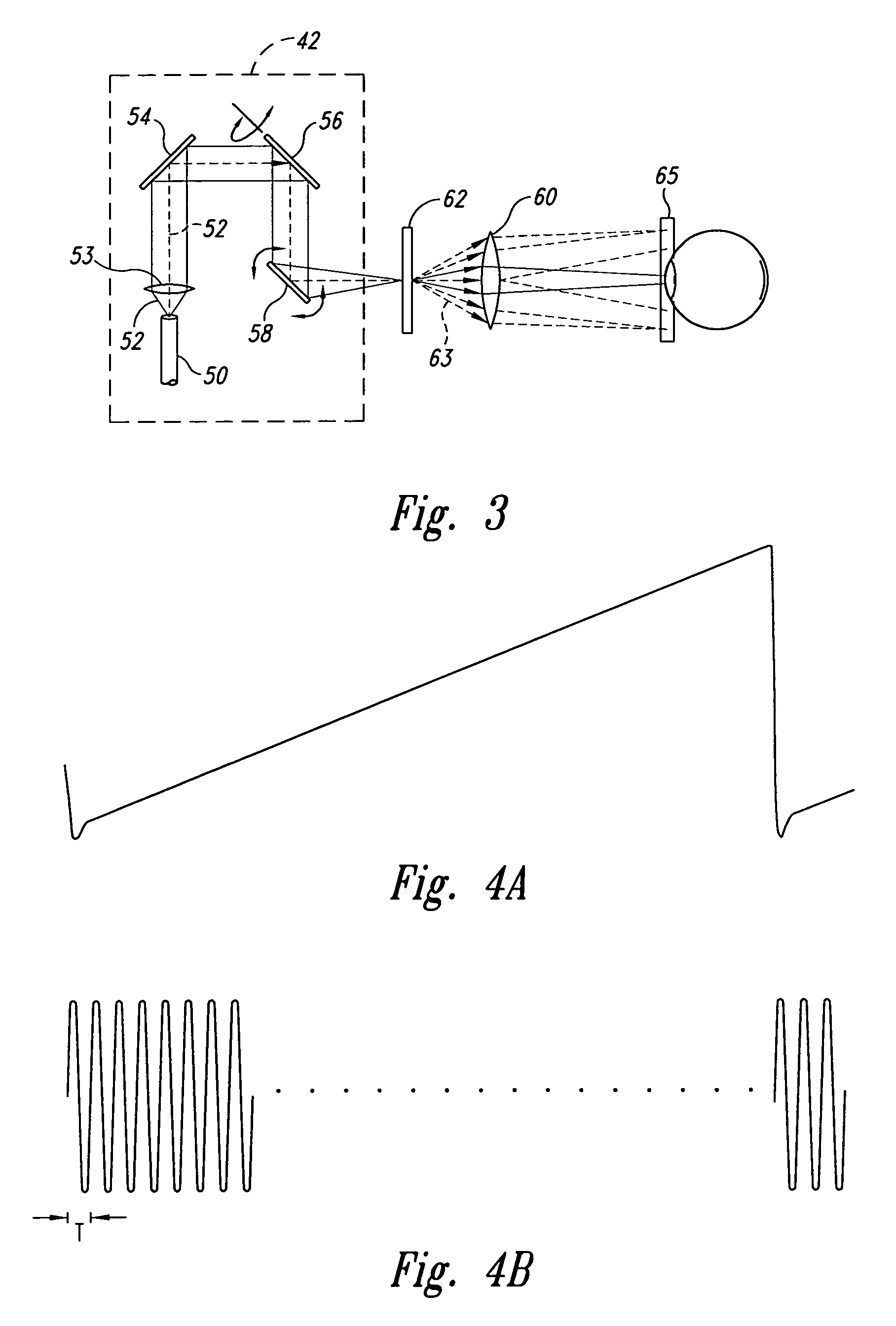
One difficulty that may arise with such displays is raster pinch, as will now be explained with reference to FIGS. 3-5.
This uneven spacing can cause the pixels to overlap or can leave a gap between adjacent rows of pixels.
Moreover, because the image information is typically provided as an array of data, where each location in the array corresponds to a respective position in the ideal raster pattern 69, the displaced pixel locations can cause image distortion.
Consequently, a large mirror and larger scan angle may produce unacceptable refresh rates.
Method used
Image
Click on the blue label to locate the original text in one second.
Reading with bidirectional positioning of images and text.
Examples
Embodiment Construction
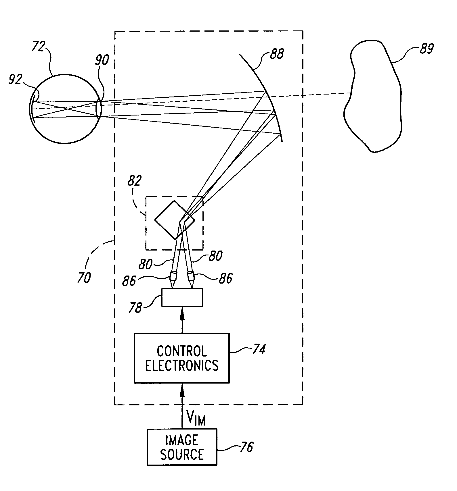
[0069]As shown in FIG. 6, a scanned beam display 70 according to one embodiment of the invention is positioned for viewing by a viewer's eye 72. While the display 70 is presented herein is scanning light into the eye 72, the structures and concepts described herein can also be applied to other types of displays, such as projection displays that include viewing screens.
[0070]The display 70 includes four principal portions, each of which will be described in greater detail below. First, control electronics 74 provide electrical signals that control operation of the display 70 in response to an image signal VIM from an image source 76, such as a computer, television receiver, videocassette player, DVD player, remote sensor, or similar device.
[0071]The second portion of the display 70 is a light source 78 that outputs modulated light beams 80, each having a modulation corresponding to information in the image signal VIM. The light source 78 may utilize coherent light emitters, such as l...
PUM
Abstract
A beam scanner is operable to scan light in two or more axes, typically in a raster pattern that includes a fast scan axis and a slow scan axis. Plural beams of light are scanned, each beam of light producing a scanned region that at least partially overlaps at least one adjoining scanned region. Scanned regions may be aligned to adjoin and overlap along a dimension corresponding to the slow scan axis. The beam scanner may comprise a scanned beam display and / or a scanned beam image capture device. In a display, the power level of overlapping displayed pixels may be scaled to provide smooth transitions between adjoining regions to improve the image quality presented to a viewer. In an image capture device, one or more detectors is operable to collect light scattered from adjoining regions and a controller is operable to produce an image from the scanned regions.
Description
CROSS-REFERENCE TO RELATED APPLICATIONS[0001]This is a continuation of application Ser. No. 10 / 768,199 filed Jan. 30, 2004, now U.S. Pat No. 7,002,716, which is a continuation of application Ser. No. 10 / 339,953, filed Jan. 10, 2003, and issued as U.S. Pat. No. 6,687,034 on Feb. 3, 2004, which is a continuation of application Ser. No. 10 / 075,679, filed on Feb. 13, 2002, and issued as U.S. Pat. No. 6,512,622 on Jan. 28, 2003, which is a divisional of application Ser. No. 09 / 893,804, filed on Mar. 23, 2001, and issued as U.S. Pat. No. 6,384,406 on May 7, 2002, which is a continuation of application Ser. No. 09 / 370,795, filed on Aug. 5, 1999, and issued as U.S. Pat. No. 6,256,131 on Jul. 3, 2001.TECHNICAL FIELD [0002]The present invention relates to scanned light devices and, more particularly, to scanned light beam displays and imaging devices for viewing or collecting images.BACKGROUND OF THE INVENTION[0003]A variety of techniques are available for providing visual displays of graphic...
Claims
Application Information
Patent Timeline
Application Date:The date an application was filed.
Publication Date:The date a patent or application was officially published.
First Publication Date:The earliest publication date of a patent with the same application number.
Issue Date:Publication date of the patent grant document.
PCT Entry Date:The Entry date of PCT National Phase.
Estimated Expiry Date:The statutory expiry date of a patent right according to the Patent Law, and it is the longest term of protection that the patent right can achieve without the termination of the patent right due to other reasons(Term extension factor has been taken into account ).
Invalid Date:Actual expiry date is based on effective date or publication date of legal transaction data of invalid patent.
Patent Type & Authority Patents(United States)
IPC IPC(8): G02B26/08
CPCG02B26/105G02B26/085
Inventor WINE, DAVID W.HELSEL, MARK P.TEGREENE, CLARENCE T.
