Hybrid office panel construction for a modular office furniture system

a modular office furniture and office panel technology, applied in the field of wall panels, can solve the problems of limited accessories which can be mounted to the individual panels that make up the spine assembly, limited to the connection of the panels, and the arrangement does not provide for complete freedom in the design of the overall workstation floor plan, so as to facilitate the reconfiguration and redesign of the work spa

Inactive Publication Date: 2007-12-25
KNOLL INC
View PDF59 Cites 41 Cited by
  • Summary
  • Abstract
  • Description
  • Claims
  • Application Information

AI Technical Summary

Benefits of technology

[0016]The present invention provides a wall construction for use in offices where it is desirable to define space, support work surfaces and storage components, attach perpendicular partitions, manage power and data cabling and terminations and allow for ease in work space reconfiguration and redesign. The objects of the invention provide improved capability to satisfy the following functional objectives: it allows for the attachment of partitions, work surfaces, storage components and accessories to the wall without regard for modularity. The panel assembly of the present invention allows for the lay in of wiring anywhere between a structural framework and removable facing panels. The present invention preserves access for lay

Problems solved by technology

Thus, the accessories which can be mounted to the individual panels that make up the spine assembly are limited to attachments at the ends of each of the wall panels, such as at the connection of one panel to another.
Additionally, if it is desired to provide an L-shaped connection or a perpendicular wall panel atta

Method used


Image

  • Hybrid office panel construction for a modular office furniture system
  • Hybrid office panel construction for a modular office furniture system
  • Hybrid office panel construction for a modular office furniture system

Examples


Embodiment Construction

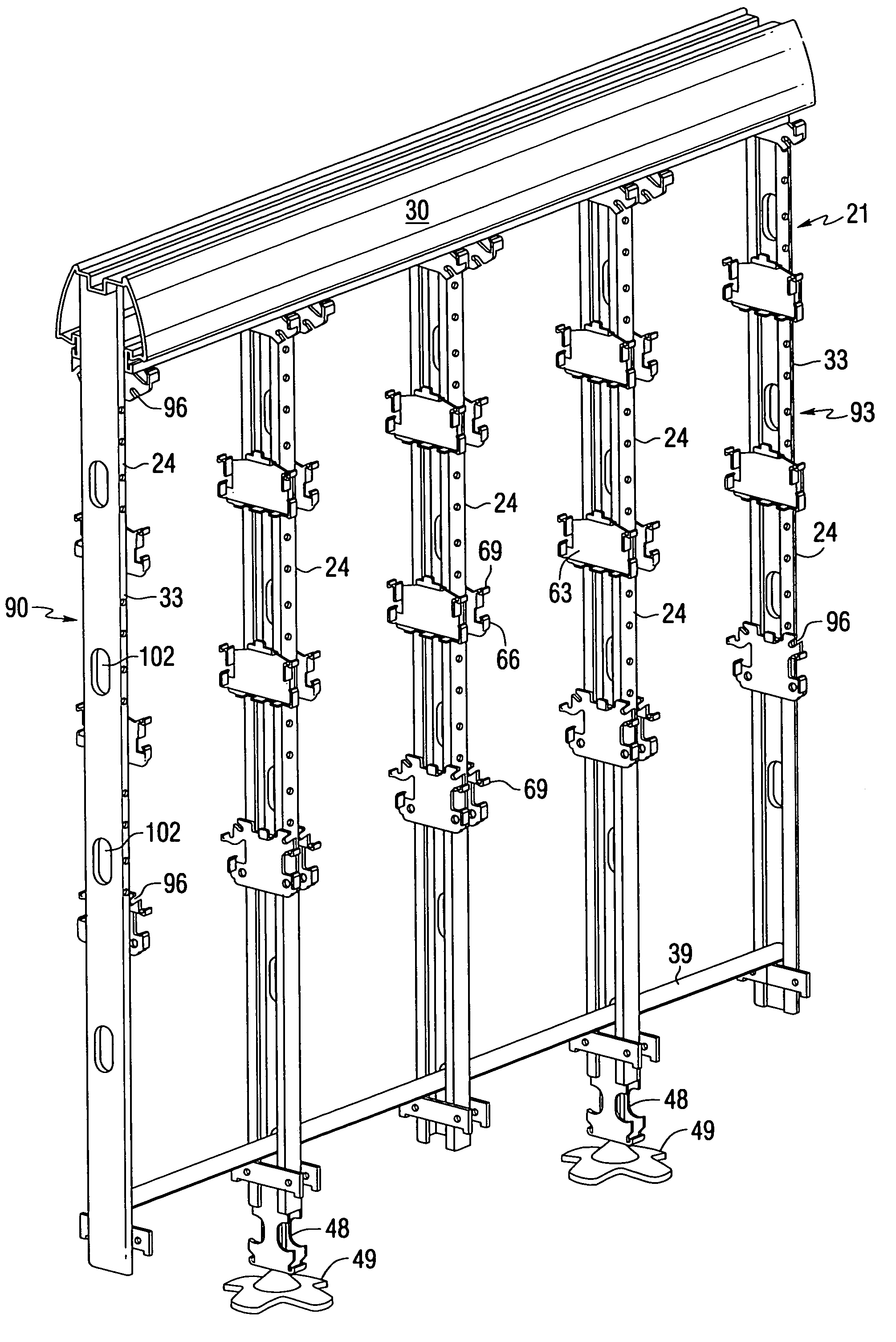
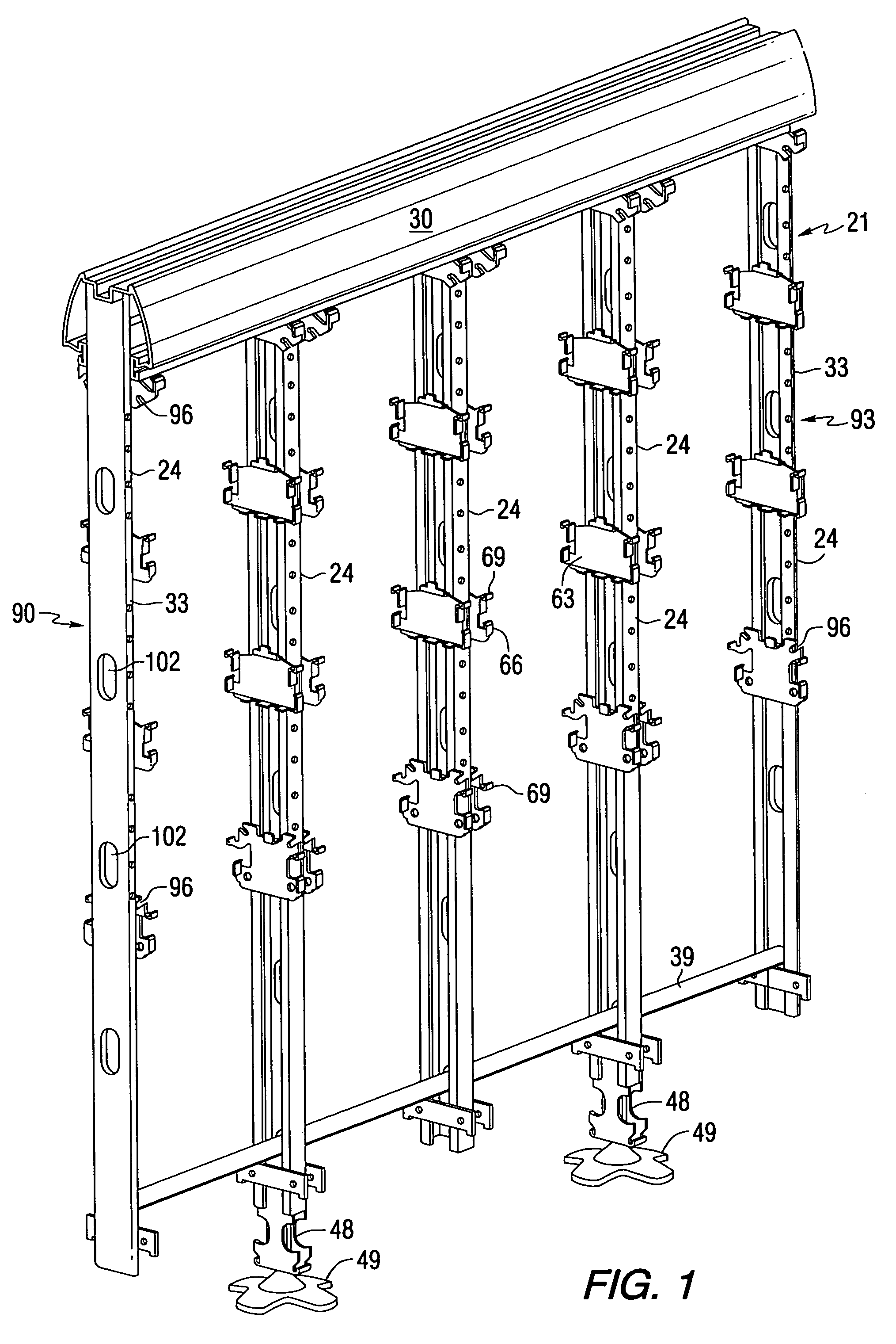
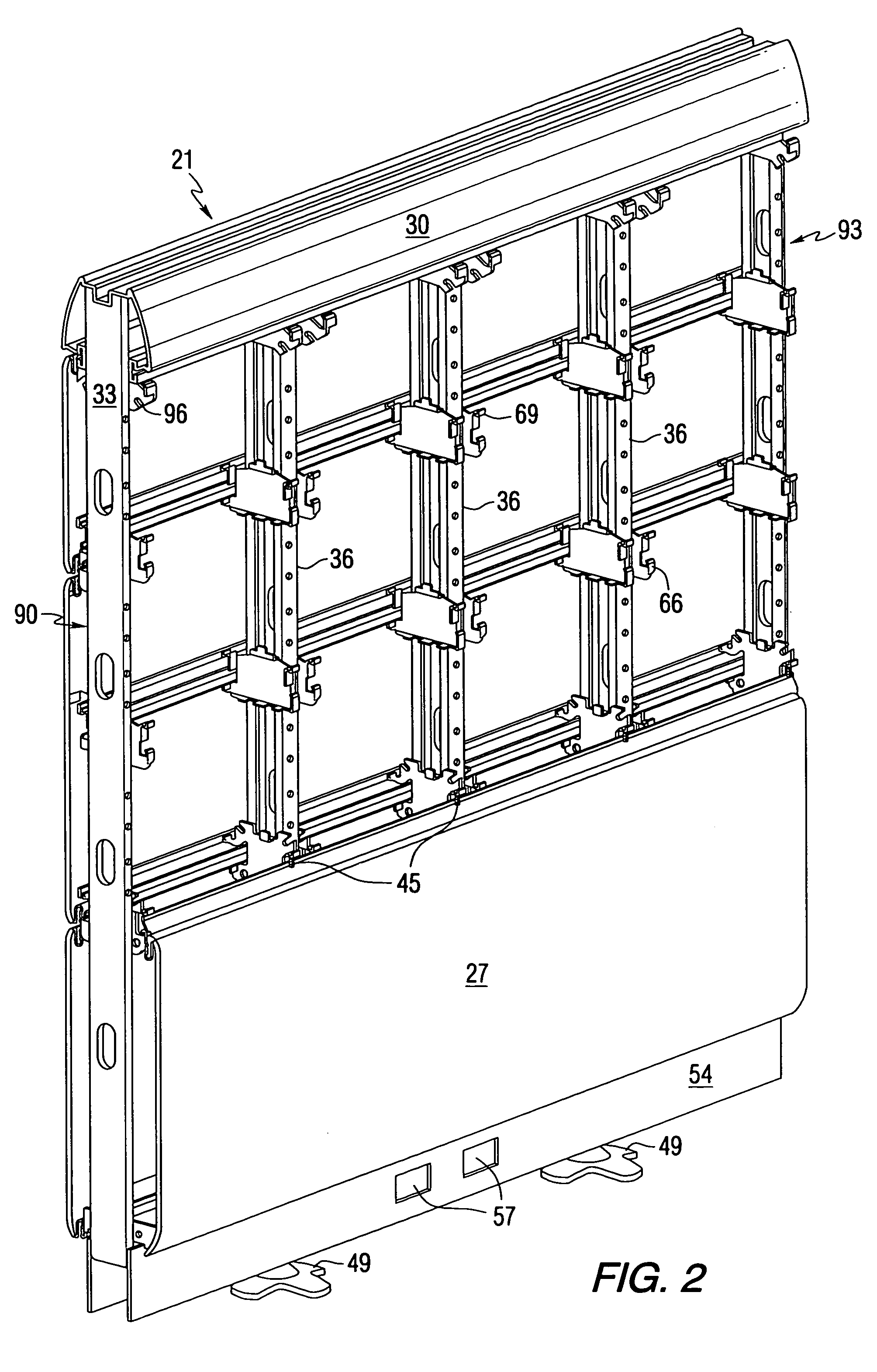
[0035]Referring now to the drawings in detail, FIGS. 1 and 2 show an individual panel assembly 21 for a spine assembly of the present invention having a substantially open structure of vertical frame members 24 (FIG. 1) which, in combination with a mechanically fastened bottom facing panel 27, and preferably through the attachment of a crown member 30 (FIG. 2), provides a rigid framework resembling a box beam structure so as to provide the various mounting capabilities of the present invention. The hybrid panel construction is generally comprised of a plurality of vertical frame members which when assembled into a panel assembly resemble conventional architectural wall stud members. The frame members of the individual panel construction comprise two end vertical members 33 and at least one vertical upright support positioned therebetween. For a typical four (4) foot wide panel assembly 21, three intermediate vertical upright supports are provided. During construction of the panel as...


PUM


Abstract

A wall spine assembly for a modular office system comprises a plurality of individual panel assemblies. Each of the panel assemblies includes a vertical support structure and mechanically affixed lower panels in a rigid box-beam structure. Facing panels are removably attached to support brackets mounted on the vertical supports. A cavity exists between the facing panels and vertical supports to permit the lay-in of cabling through the office system. A crown member is provided on the top of the vertical support and is adapted to receive brackets for the mounting of accessories above a desk or other work surface attached to the panel. The panels, and especially the crown, permit the mounting of office components such as shelves, storage cabinets, lighting fixtures and the like anywhere along the horizontal length of the wall. A horizontally telescoping vertical end post is also provided.

Description

[0001]This application is a continuation of application Ser. No. 08 / 864,138, filed May 28, 1997 now U.S. Pat. No. 6,167,664.BACKGROUND OF THE INVENTION[0002]1. Field of the Invention[0003]The present invention relates to wall panels for use in modular open office systems, and more particularly to a multi-functional structural beam arrangement which rigidifies an open framework used to support removable facing panels and modular office components.[0004]2. Description of the Prior Art[0005]The use of modular open office furniture systems has become quite prevalent in interior office design. One aspect of these open office systems is a single free standing wall unit, or spine, which forms the main structural element of the open office system. The main function of the spine assembly is to support a work surface or desktop for a user, and as a means for routing data, communication and power cables through the open office system to provide cabling for the desktop units. In addition to the...

Claims


Application Information

Patent Timeline
IPC IPC(8): E04C2/52A47B21/00E04B2/74
CPCA47B21/06E04B2/7425E04B2002/7462E04B2002/749E04B2002/7483E04B2002/7488E04B2002/7466
Inventor REUTER, ROBERT E.ROZIER, JR., CHARLES P.BULLWINKLE, WALLACE C.
Owner KNOLL INC
Why Eureka
Try Eureka