Strike-off beam and spreader plow assembly for placer/spreader

a spreader/spreader and assembly technology, applied in the direction of roads, roads, construction, etc., can solve the problems of wasting time and wasting time in relocating the receiving conveyor, and the prior art has failed to recognize the utility of such a removable attachment assembly

Active Publication Date: 2007-12-25
GUNTERT & ZIMMERMAN CONSTR DIV
View PDF9 Cites 6 Cited by
  • Summary
  • Abstract
  • Description
  • Claims
  • Application Information

AI Technical Summary

Benefits of technology

[0011]An improvement according to the present invention comprises a strike-off beam and spreader plow assembly for trailing attachment to the frame of the placer / spreader. The placer / spreader has a strike-off beam spanning the frame, and first and second attachment points on either side of the frame, the attachment points mating with the attachment bars of the strike-off beam. Attachments on the strike-off beam attach to either of the first and second attachment points on opposite sides of the frame. A separate spreader plow track is attached at the upper surface of a longitudinal support beam which supports the strike-off beam and has a spreader plow car movable along the spreader plow track from end to end of the plow track. A spreader plow blade is dependently mounted from the spreader plow car for plowing concrete side to side in advance of the strike-off beam. The improved spreader plow and strike-off beam can be quickly and easily reversibly mounted on opposite sides of the frame to receive concrete from either side of the machine without requiring conveyor disassembly.
[0013]We avoid the necessity of relocating the receiving conveyor when the location of the access road changes from one side to the opposite side of the machine. Relocating the receiving conveyor is extremely time-consuming and requires a large crane assist as opposed to relocating the strike-off beam with the spreader plow, which can be transferred rapidly without the need for a crane. Furthermore, by using a spreader plow, as opposed to an auger, in conjunction with the strike-off beam, the spreader plow with strike-off can be retracted close enough to the tractor frame so that the strike-off does not require separate removal for transport.

Problems solved by technology

The prior art has failed to recognize the utility of such a removably attached strike-off / spreader plow assembly.
Relocating the receiving conveyor is extremely time-consuming and requires a large crane assist as opposed to relocating the strike-off beam with the spreader plow, which can be transferred rapidly without the need for a crane.

Method used


Image

  • Strike-off beam and spreader plow assembly for placer/spreader
  • Strike-off beam and spreader plow assembly for placer/spreader
  • Strike-off beam and spreader plow assembly for placer/spreader

Examples


Embodiment Construction

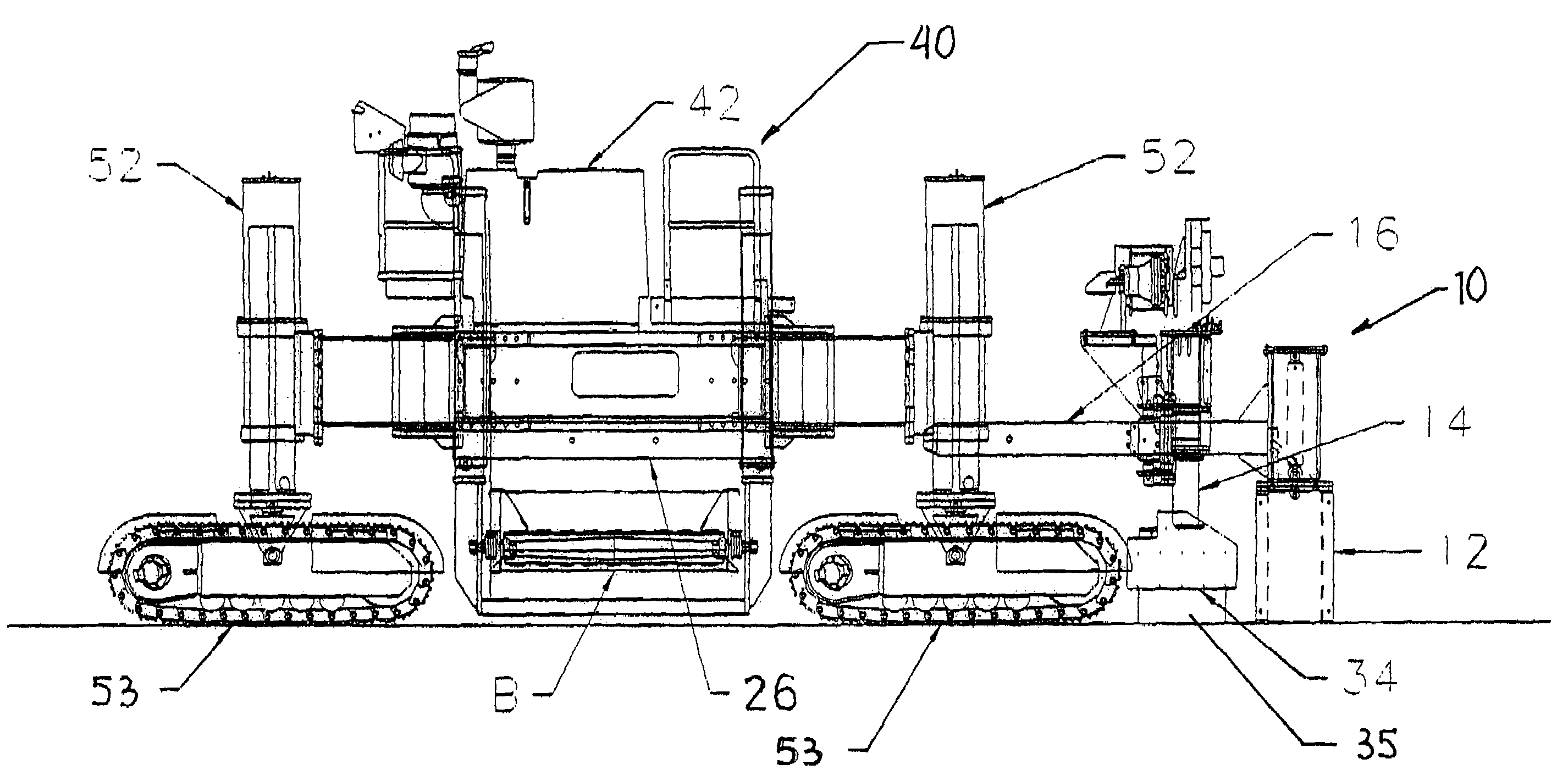
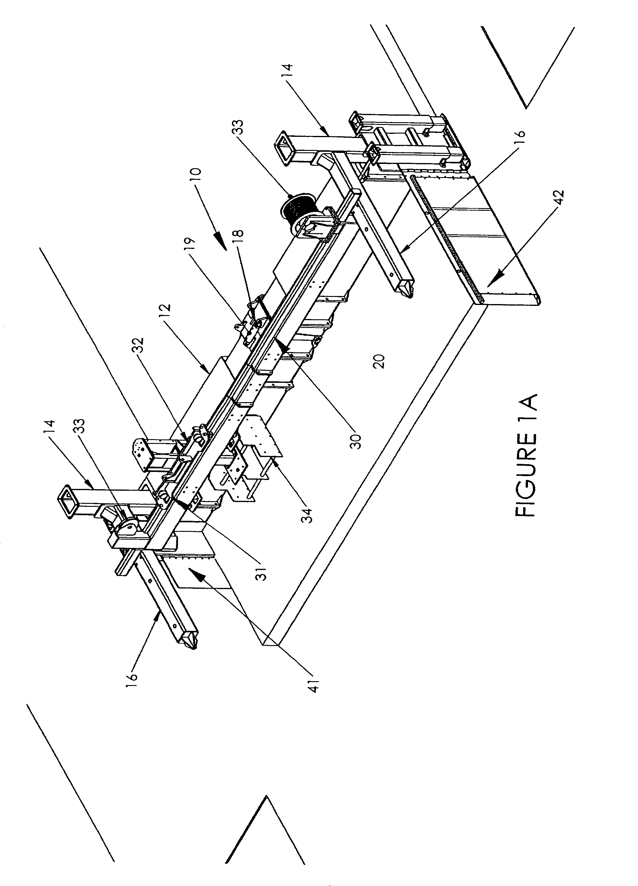
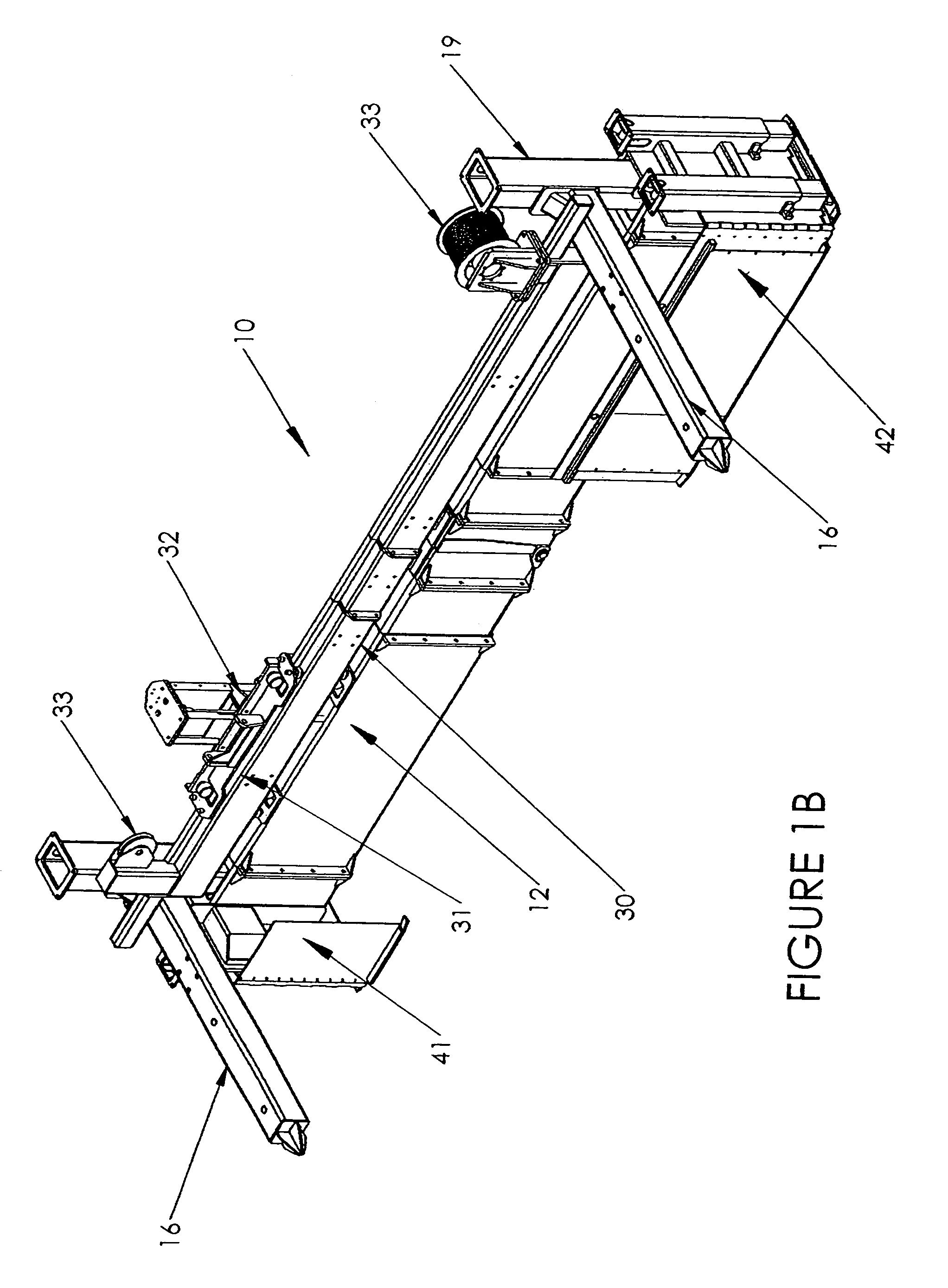
[0021]Referring to FIG. 1A, the strike-off beam and spreader plow assembly 10 is illustrated in perspective. Strike-off beam 12 has vertical supports 14 located at either end or side spanning placed concrete 20. Centrally of strike-off beam 12 there is placed hinge 18 which is articulated by hydraulic cylinder 19 to apply a berm profile to strike-off beam 12.

[0022]Vertical supports 14 have longitudinally extending male couplers 16 on either side of strike-off beam and spreader plow assembly 10. It is these male couplers 16 which enable engagement of the strike-off beam and spreader plow assembly 10 to either side of a placer / spreader.

[0023]Supported on male couplers 16 is spreader plow assembly 30. Spreader plow assembly 30 includes a spanning rail 31, a spreader plow car 32 with a plow blade 34 which rides on rail 31 in spanning movement, and a reel and cable (such as a wire rope winch) movement system 33 for moving the depending spreader plow blade 34. When strike-off beam and spr...


PUM


Abstract

In combination with a placers / spreader having a frame including at least two side bolsters standing parallel to the subgrade path and at least two cross beams spanning the subgrade path forming a conveyor supporting structure. A rail system is attached spanning the frame, and has a roll in / roll out conveyor with a cantilevered support at one of the side bolsters and a support for attachment to and support from the rail system. The conveyor moves in traversing motion across the frame to distribute concrete. The improvement comprises a strike off beam and spreader plow assembly for trailing attachment to the frame of a placer / spreader. We thus disclose a strike off beam with spreader plow assembly which can be removably attached to either side of a placer / spreader to avoid the necessity of relocating the receiving conveyor when the location of the access road changes from one side to the other or direction of spreading changes. We additionally disclose a method of operation the strike off beam from a placer / spreader to prevent the accumulation of excess concrete the path of the following paver.

Description

BACKGROUND OF THE INVENTION[0001]This invention relates to a strike-off beam and spreader plow assembly which can alternately be placed and supported spanning a subgrade to be paved behind a placer / spreader. More particularly, mounts are provided to removably mount the strike-off beam and spreader plow on either spanning side of the placer / spreader to permit the loading of concrete from either side of the placer / spreader. The mounts permit rapid transfer of the strike-off beam and spreader plow assembly to enable the placer / spreader to receive concrete from access roads on opposite sides of a subgrade being paved.[0002]Slipform pavers are commonly utilized for paving reinforced and non-reinforced concrete roadways and airfield pavements. It is common practice for the concrete delivery trucks to back up on the subgrade and dump the contents of the truck on the subgrade in the path of a slipform paver and thereafter spread the placed concrete into the final profile of the specified co...

Claims


Application Information

Patent Timeline
Patent Type & Authority Patents(United States)
IPC IPC(8): E01C19/12E01C19/00
CPCE01C19/185E01C19/48E01C19/42E01C2301/18
Inventor GUNTERT, JR., RONALD M.FRANCIS, RICK
Owner GUNTERT & ZIMMERMAN CONSTR DIV
Why Eureka
Try Eureka