AI technical title is built by Patsnap AI team. It summarizes the technical point description of the patent document.
a multi-mode, lighter technology, applied in the field of lighters, can solve the problems of obstructing and/or preventing the actuating member
Inactive Publication Date: 2007-12-25
SOC DITE SOC BIC
View PDF73 Cites 13 Cited by
Summary
Abstract
Description
Claims
Application Information
AI Technical Summary
This helps you quickly interpret patents by identifying the three key elements:
Problems solved by technology
Method used
Benefits of technology
Benefits of technology
[0011]According to another exemplary embodiment of the present invention, the lighter may include a housing having a supply of fuel in communication with a nozzle, an ignition mechanism operable to create a spark to ignite the fuel proximate the nozzle, an actuating member extending from the housing and movable to release the fuel from the supply of fuel, and an inhibiting member extending from the housing and biased to a first position, wherein the inhibiting member is movable to a second position to resist, obstruct and / or prevent the ignition and / or the release of fuel from the nozzle. The lighter may further include an elastic element for biasing the inhibiting member to the first position. Additionally or alternatively, the lighter may include a conduit extending from the supply of fuel to the nozzle, and the fuel may be obstructed from flowing through at least a portion of the conduit when the inhibiting member is in the second position. For example, a piston may be associated with the conduit, and the piston may obstruct the fuel from flowing through at least a portion of the conduit when the inhibiting member is in the second position. The piston may be disposed within the conduit, although other configurations are contemplated. The lighter may further include a junction connecting a first portion of the conduit to a second portion of the conduit, and the piston may be disposed within the junction. The piston may be normally biased toward a first position in which the fuel flows through the junction. For example, an elastic element may be provided to bias the piston toward the first position. Moving the inhibiting member to the second position may move the piston to a second position in which fuel is obstructed and / or prevented from flowing through the junction.
Problems solved by technology
Moving the inhibiting member a predetermined distance may resist, obstruct and / or prevent the actuating member from performing at least one step in igniting the fuel.
For example, moving the inhibiting member the predetermined distance may resist, obstruct and / or prevent the actuating member from moving sufficiently to perform at least one step in igniting the fuel.
Further, alternatively or additionally, moving the inhibiting member the predetermined distance may resist, obstruct and / or prevent the actuating member from creating a spark to ignite the fuel.
Method used
Image
Click on the blue label to locate the original text in one second.
Reading with bidirectional positioning of images and text.
Examples
Embodiment Construction
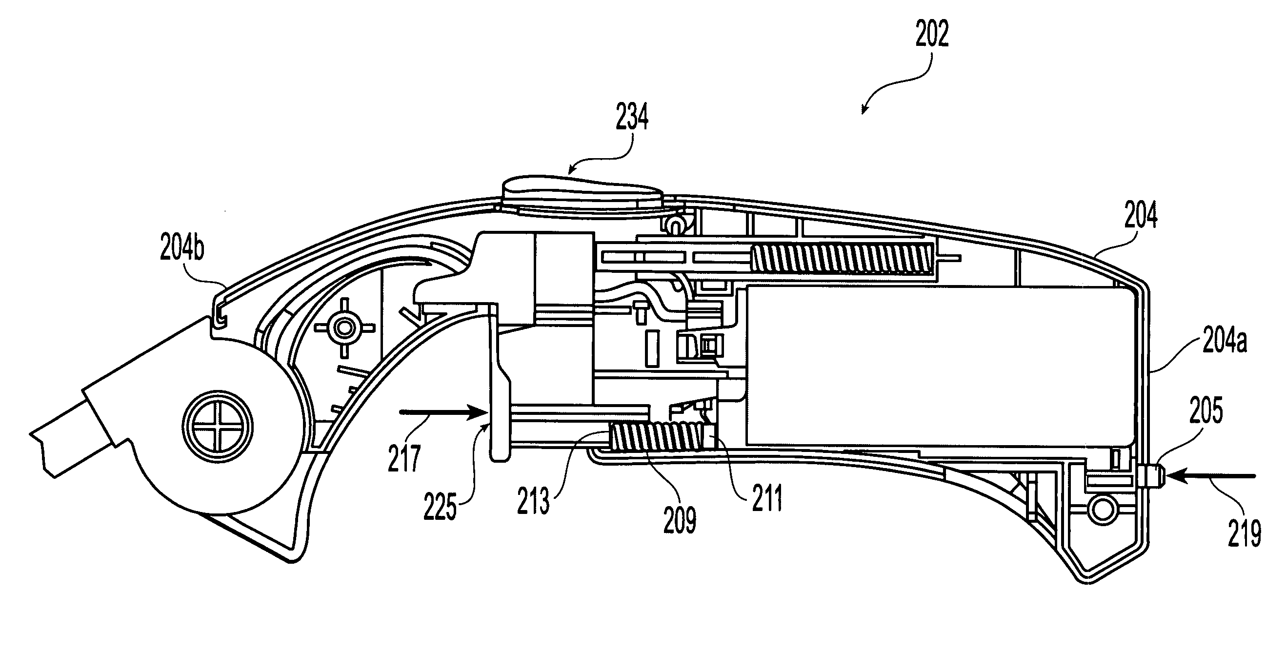
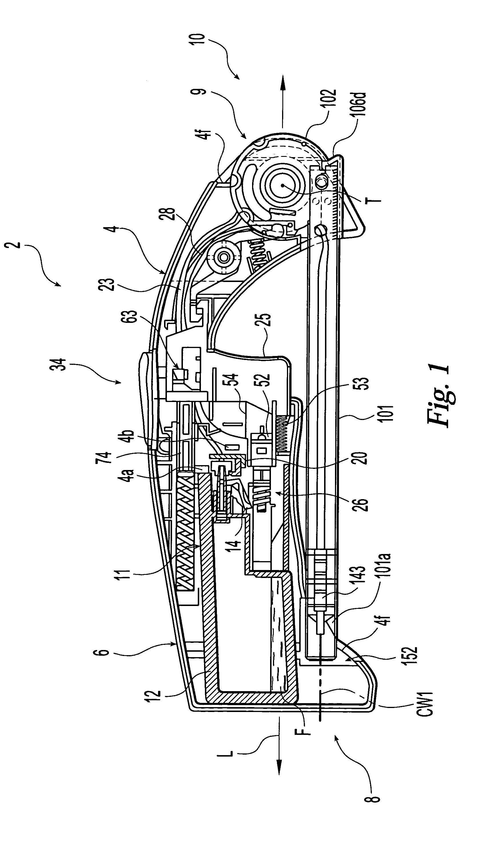
[0051]Turning to FIG. 1, an embodiment of a utility lighter 2 constructed in accordance with the present invention is shown with the understanding that those of ordinary skill in the art will recognize many modifications and substitutions which may be made to various elements. While the invention will be described with reference to a utility lighter, one of ordinary skill in the art could readily adapt the teaching to conventional pocket lighters and the like.
[0052]Lighter 2 generally includes a housing 4 which may be formed primarily of molded-rigid-polymer or plastic materials such as acrylonitrile butadiene styrene terpolymer or the like. The housing 4 may also be formed of two-parts that are joined together by techniques known by those of ordinary skill in the art, such as ultrasonic welding.
[0053]Housing 4 includes various support members, such as support member 4a discussed below. Further support members are provided in the lighter 2 for various purposes, such as supporting co...
PUM
Abstract
The present invention is directed to a lighter including a housing having a supply of fuel, an actuating member extending from the housing and being movable to selectively perform at least one step in igniting the fuel, and an inhibiting member extending from the housing. Moving the inhibiting member a predetermined distance resists, obstructs and / or prevents the actuating member from performing at least one step in igniting the fuel. For example, moving the inhibiting member the predetermined distance may resist and / or prevent movement of the actuating member, may obstruct and / or prevent the release of fuel, and / or may resist and / or prevent the creation of a spark to ignite the fuel. Various other features which improve the functioning of the lighter may be provided separately or in combination.
Description
CROSS-REFERENCE TO RELATED APPLICATIONS[0001]The present application is a continuation-in-part of U.S. patent application Ser. No. 10 / 647,505, filed Aug. 26, 2003, now U.S. Pat. No. 6,971,870 which is a continuation-in-part of U.S. patent application Ser. No. 10 / 389,975, filed Mar. 18, 2003, now U.S. Pat. No. 6,908,302, which is a continuation-in-part of U.S. patent Ser. No. 10 / 085,045, now U.S. Pat. No. 6,726,469, filed Mar. 1, 2002, which is a continuation-in-part of both U.S. patent application Ser. No. 09 / 817,278 now U.S. Pat. No. 6,916,171, and U.S. patent application Ser. No. 09 / 819,021, now U.S. Pat. No. 6,488,492, both of which were filed on Mar. 27, 2001, and both of which are continuation-in-part applications of U.S. patent application Ser. No. 09 / 704,689, now U.S. Pat. No. 6,491,515, filed Nov. 3, 2000. The contents of these six applications are expressly incorporated herein by reference thereto.TECHNICAL FIELD OF THE INVENTION[0002]The present invention generally relates...
Claims
Application Information
Patent Timeline
Application Date:The date an application was filed.
Publication Date:The date a patent or application was officially published.
First Publication Date:The earliest publication date of a patent with the same application number.
Issue Date:Publication date of the patent grant document.
PCT Entry Date:The Entry date of PCT National Phase.
Estimated Expiry Date:The statutory expiry date of a patent right according to the Patent Law, and it is the longest term of protection that the patent right can achieve without the termination of the patent right due to other reasons(Term extension factor has been taken into account ).
Invalid Date:Actual expiry date is based on effective date or publication date of legal transaction data of invalid patent.

