
Automatic performance apparatus and automatic performance program

a technology of automatic performance and performance apparatus, applied in the direction of electrophonic instruments, instruments, etc., can solve the problems of inability to carry out expressive ensemble performance with a sense of uniformity, large difference in the progress of performance between a plurality of parts,

Inactive Publication Date: 2008-01-01
YAMAHA CORP
View PDF7 Cites 9 Cited by
  • Summary
  • Abstract
  • Description
  • Claims
  • Application Information

AI Technical Summary

Benefits of technology

This solution achieves expressive ensemble performance with a sense of uniformity by synchronizing the progression of musical tones and adjusting tempo dynamically, reducing differences in performance tempo between master and slave operating elements.

Problems solved by technology

In the above conventional performance apparatus, however, the performance of each part is independently controlled through operation by each operator, and hence, for example, if each operator changes the performance tempo (progress) of a part assigned to an operating element according to his / her feeling about the motif of a piece of music, there is a great difference in the progress of performance between a plurality of parts.
As a result, the performance of a piece of music composed of a plurality of parts lacks uniformity, and therefore it is impossible to carry out expressive ensemble performance with a sense of uniformity.

Method used


Image

  • Automatic performance apparatus and automatic performance program
  • Automatic performance apparatus and automatic performance program
  • Automatic performance apparatus and automatic performance program

Examples


case 1

(Case 1)

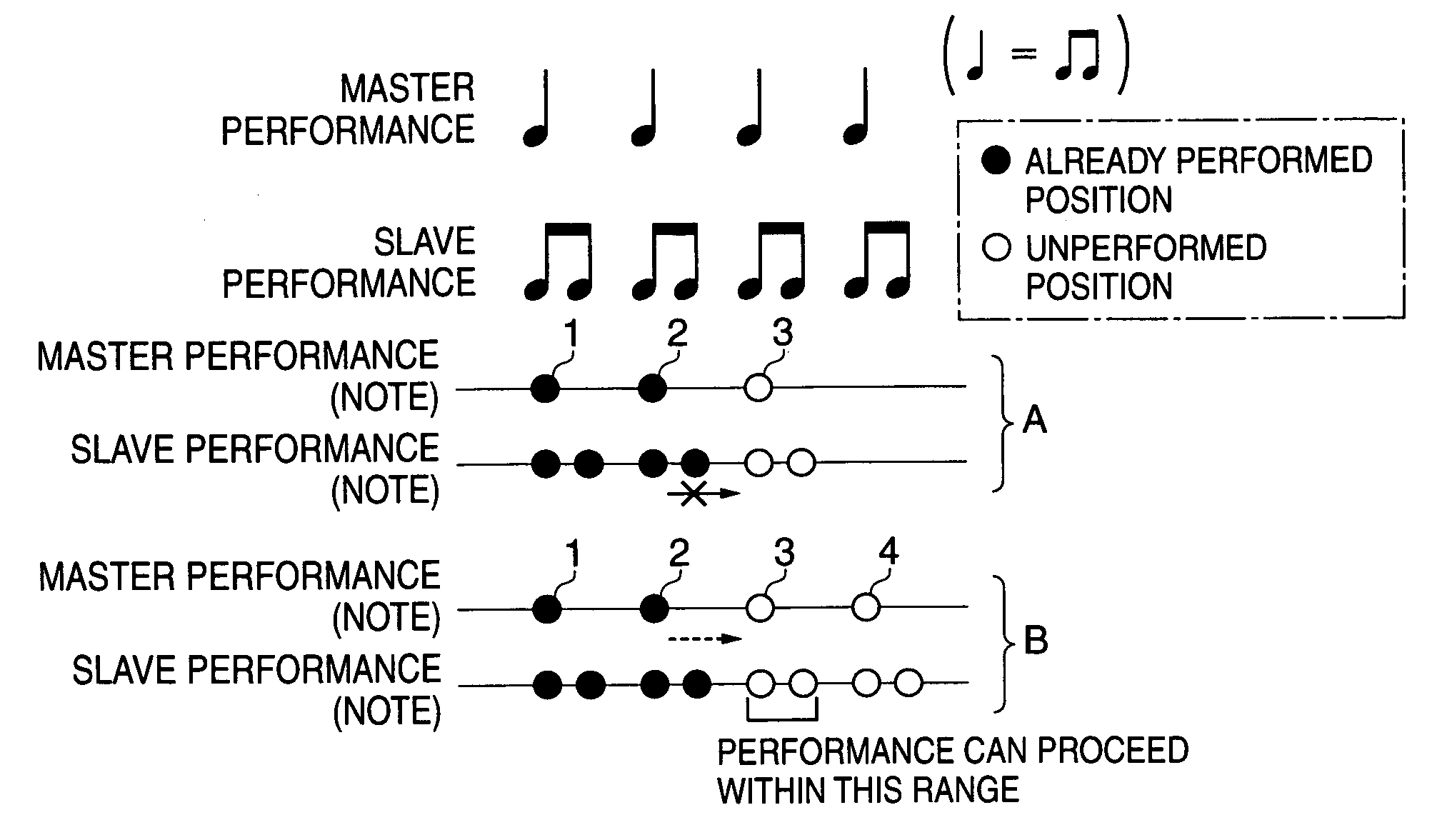
[0116]FIG. 13 is a view useful in explaining a performance process in a case 1 in the multiple operating element performance mode.

[0117]The CPU 301 constantly checks the next performance position of the master operating element (operating element as the master) 1-1 (the position at which a sounding event is to be processed next) to provide control such that the current performance position (the position at which a current sounding event is being processed) of the slave operating element (operating element as the slave) 1-2 does not go beyond the next performance position of the master operating element 1-1. Namely, the CPU 301 provides control such that the slave performance does not proceed ahead of the master performance. For example, as shown by an example A in FIG. 13, at a time point the CPU 301 receives operation information from the master operating element 1-2, if the operation of the slave operating element 1-2 is detected in the case where the master performance ha...

case 2

(Case 2)

[0118]FIG. 14 is a view useful in explaining a performance process in a case 2 in the multiple operating element performance mode.

[0119]When the operation of the slave operating element 1-2 is detected only in timing corresponding to a part of a piece of music where the performance of the melody part is interrupted and only the accompaniment part is performed, such as during an interlude in a piece of music, as shown by an example A in FIG. 14, the CPU 301 causes the slave performance to proceed in the timing in which the operation of the slave operating element 1-2 is detected. However, the slave performance can be caused to proceed only within the part of the piece of music where only the accompaniment part is performed. In other words, as shown by an example B in FIG. 14, the slave performance can be caused to proceed to a position immediately before an unperformed position “1” where the master performance is resumed. It should be noted that whether the performance positi...

case 3

(Case 3)

[0120]FIG. 15 is a view useful in explaining a performance process in a case 3 in the multiple operating element performance mode.

[0121]In the case where the operation of the slave operating element 1-2 is detected at the same time when the operation of the master operating element 1-1 is detected, or is detected within a predetermined period of time (such as 300 ms) after the operation of the master operating element 1-1 is detected, the CPU 301 causes the slave performance in the timing in which the operation of the slave operating element 1-2 has been detected. For example, as shown by an example A in FIG. 15, if the operation of the slave operating element 1-2 is detected at the same time when the operation of the master operating element 1-1 is detected when the slave performance has proceeded to a position immediately before an unperformed position “3” of the master performance, the CPU 301 causes the master performance to proceed to a performance position “3” and caus...


PUM


Abstract

An automatic performance apparatus which enables expressive ensemble performance to be carried out with a sense of uniformity. Operation signals according to operation by at least one operator, and identification information for identifying a plurality of operating elements are output from these operating elements. Operation-related information indicative of the relationship between respective ones of the plurality of operating elements and respective ones of a plurality of channels, and the master-slave relationship between the plurality of operating elements are stored in a storage. When the operation signals and the identification information are output from the plurality of operating elements, the operation-related information is referred to determine corresponding ones of the channels to the identification information, a sounding event of a musical tone to be sounded next is read out from the performance data for each of the corresponding ones of the channels, and a sounding process on the readout sounding event is carried out by a sounding processing device. The sounding process is controlled such that the position of a sounding event corresponding to at least one of the operating elements as a slave never goes beyond the position of a sounding event corresponding to one of the operating elements as a master, which is to be processed next.

Description

BACKGROUND OF THE INVENTION[0001]1. Field of the Invention[0002]The present invention relates to an automatic performance apparatus and an automatic performance program which enable ensemble performance to be carried out with ease.[0003]2. Description of the Related Art[0004]In recent years, various types of performance apparatuses which enable even a beginning musical instrument player who has no experience of playing a musical instrument to enjoy ensemble performance in an easy way have been developed in the field of electronic musical instruments. For example, there has been proposed a performance apparatus which respectively assigns a plurality of musical instrument parts constituting a piece of music for automatic performance to be carried out based on automatic performance data to a plurality of operating elements, and detects the operative states of the respective operating elements (such as “swinging”, “patting”, and “tilting”) so that volume, tone color, performance tempo, ...

Claims


Application Information

Patent Timeline
Patent Type & Authority Patents(United States)
IPC IPC(8): G10H7/00G10H1/00G10H1/18
CPCG10H1/0008G10H2220/201G10H2240/056G10H2240/211
Inventor NISHITANI, YOSHIKIISHIDA, KENJI
Owner YAMAHA CORP
Learn More