Mechanically regulated timepiece

a timepiece and mechanical technology, applied in the field of mechanically regulated time indicators, can solve the problems of difficult customisation (decoration, design, frequency) if not impossible, then certainly difficult, and the disadvantage of being understood as components in the construction of the tourbillon, so as to achieve the maximum visibility of the moving parts

Inactive Publication Date: 2008-01-08
WATCH U LICENSE
View PDF14 Cites 14 Cited by
  • Summary
  • Abstract
  • Description
  • Claims
  • Application Information

AI Technical Summary

Benefits of technology

[0014]Compared with a conventional mechanically regulated time indicator of the balance spring tourbillon type, the invention presents the following advantages:
[0015]The time indicator is provided with a cantilevered bearing of the ball bearing type thus permitting a particularly simple and robust construction that requires fewer components.
[0016]The time indicator is mounted in such a way that it is visible from the dial side and has no part overlapping the cage. This enables a particularly aesthetic, easily obtainable and slim construction. This construction is adapted for large and small calibres.

Problems solved by technology

All these tourbillon constructions are known to present the disadvantage of being understood as components, which are indissociable from the watch movement.
This makes their final adjustment tricky and their customisation (decoration, design, frequency) if not impossible, then certainly difficult.

Method used


Image

  • Mechanically regulated timepiece
  • Mechanically regulated timepiece
  • Mechanically regulated timepiece

Examples


Embodiment Construction

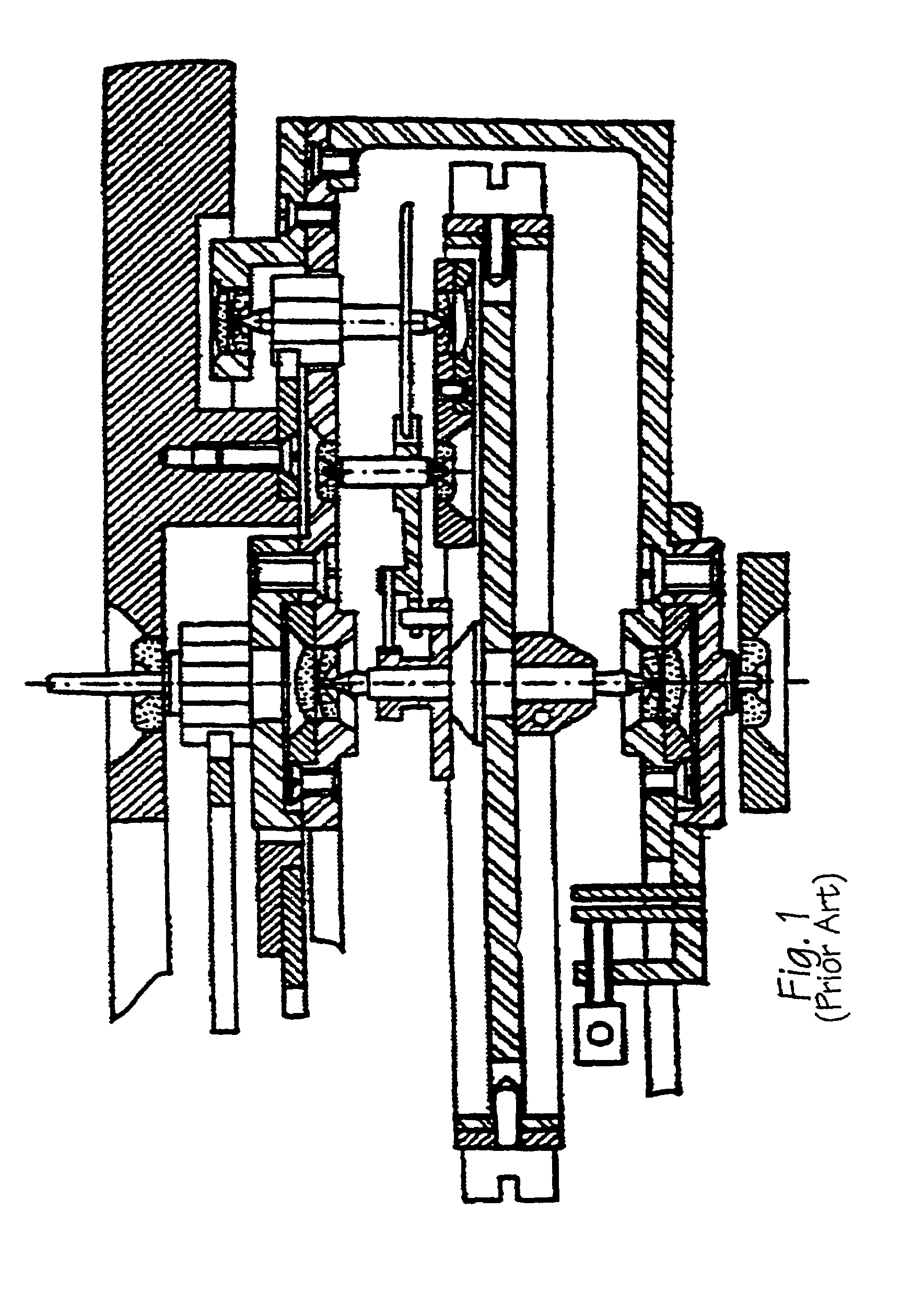
[0020]FIG. 1 is a cross-sectional view of a tourbillon regulated time indicator,

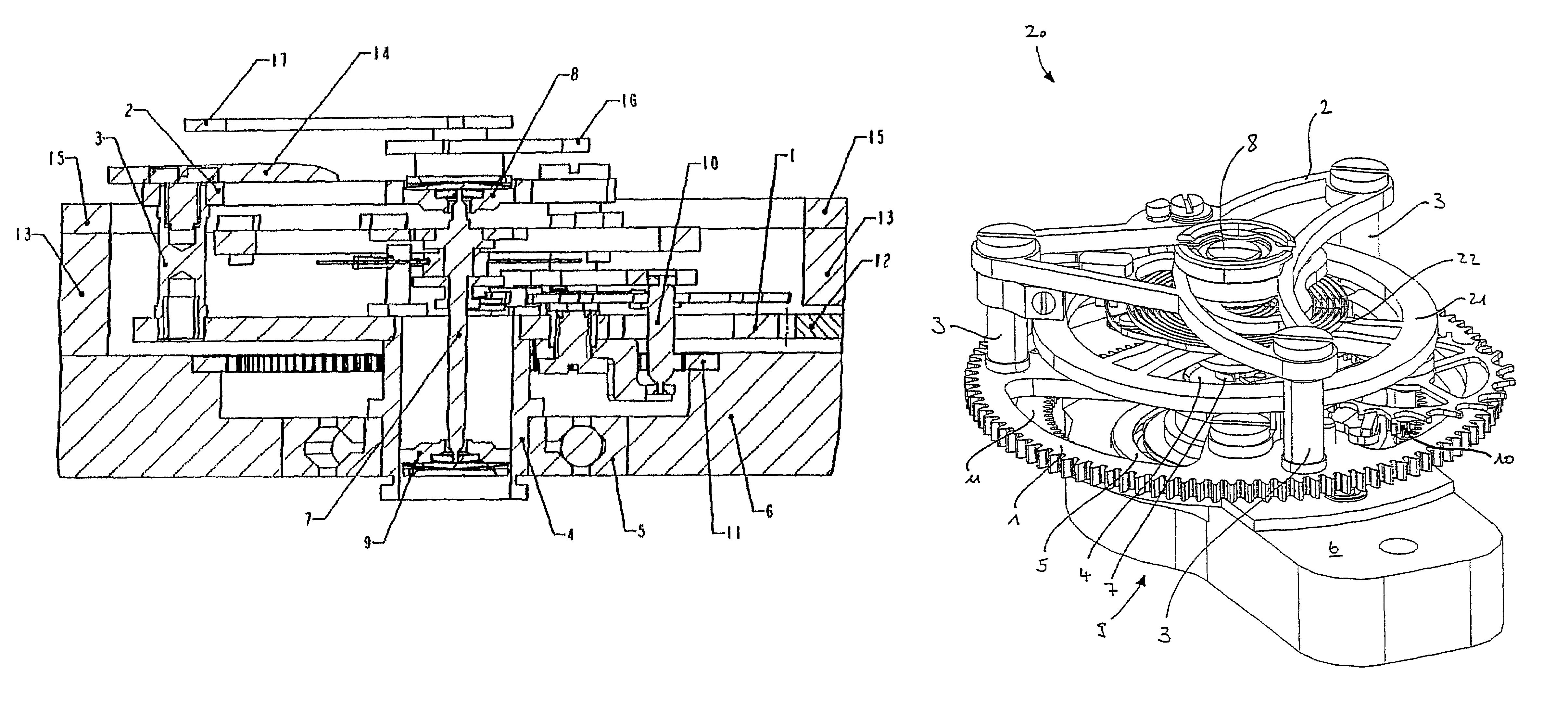
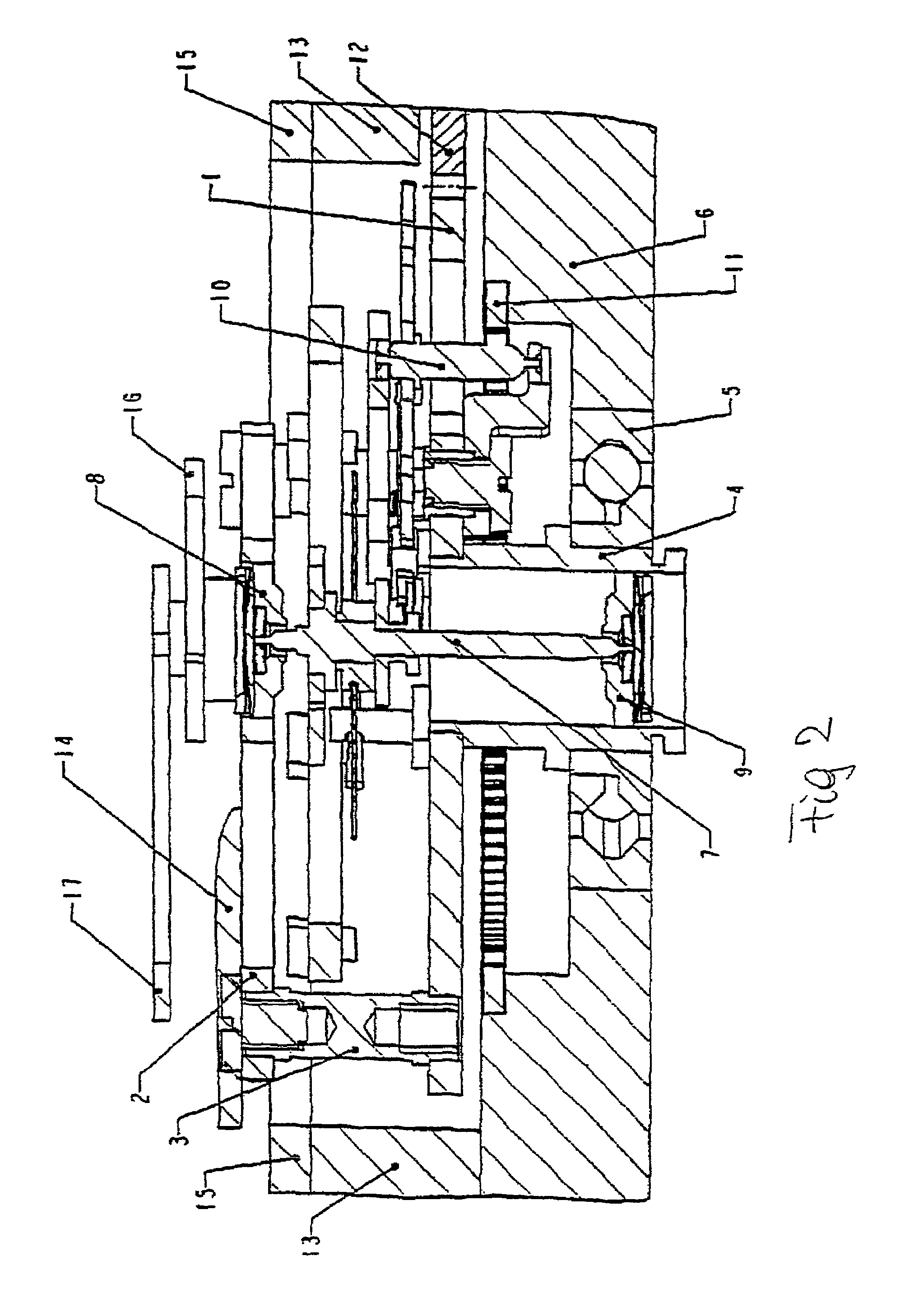
[0021]FIG. 2 is a cross-sectional side view of the detail of an exemplary embodiment of a regulated time indicator according to the invention,

[0022]FIG. 3 is a top view of the detail of an exemplary embodiment of a regulated time indicator according to FIG. 2.

[0023]FIG. 4 is a perspective view of a tourbillon module for a time indicator according to the invention.

[0024]FIG. 5 is a view of the rear side of a movement carrying the tourbillon module according to FIG. 4.

[0025]FIG. 6 is a cross-sectional view of the detail along the line D-D of FIG. 5.

[0026]FIG. 1 is a cross-sectional view of a balance spring tourbillon regulated time indicator. In this device, a balance, its spiral spring and the tourbillon collet are assembled inside a turning cage that rotates at a speed of 60 sec. per revolution. The whole cage turns around a double bearing gear.

[0027]FIGS. 2 and 3 are different views of detail of the exe...


PUM


Abstract

The invention concerns a timepiece with mainspring of the so-called fly tourbillon type, the tourbillon having a balance bridge (2) forming a cage with a collet (1) and a single protruding ball bearing (5) supporting said so-called fly tourbillon assembly. Said so-called fly tourbillon assembly is visible on the dial side (15) and is designed as an independent tourbillon module. Said tourbillon module is separable from the clockwork (13) by being detached on the rear side of the clockwork (13) and by being removed on that same side.

Description

BACKGROUND OF THE INVENTION[0001]1. Technical Field[0002]The present invention relates to a mechanically regulated time indicator particularly suited for use in wrist-watches.[0003]2. Related Art[0004]The present invention falls into the family of so-called tourbillon time indicators. The conventional type of such a time indicator is represented by the Bréguet Tourbillon from 1795. In this device, a balance, its spiral spring and its escapement are assembled in the interior of a turning cage, the rotational speed of which is one revolution per 60 seconds. The cage turns about a double bearing gear.[0005]In the development of wristwatches, a reduction in the number of bearings is observed. The patent GB-21421 from 1892 describes a tourbillon cantilevered in a single large bearing. Patent CH-353679 from 1961 describes a cantilevered bearing construction of the ball bearing type wherein the ball bearing replaces the thick smooth bearing used up to that time. Nowadays, cantilevered bear...

Claims


Application Information

Patent Timeline
Patent Type & Authority Patents(United States)
IPC IPC(8): G04B15/00G04B19/20G04B17/28G04B33/08
CPCG04B17/285
Inventor MOCK, ELMARGUERRY, BEGONAMARIOTTO, ELIO
Owner WATCH U LICENSE
Why Eureka
Try Eureka