Power seat slide apparatus for a vehicle

a technology for power seats and slide apparatuses, which is applied in the direction of machine supports, movable seats, roofs, etc., can solve the problems of increasing the weight and cost of the power seat slide apparatus, enlarging the lower rail and the upper rail, and affecting the appearance of the lower rail

Active Publication Date: 2008-02-05
AISIN SEIKI KK
View PDF15 Cites 42 Cited by
  • Summary
  • Abstract
  • Description
  • Claims
  • Application Information

AI Technical Summary

Problems solved by technology

In the above-described circumstances, the internal space of the lower rail has to be enlarged in the lateral direction of the vehicle, which may leads to enlarging the lower rail and the upper rail and to an increase in weight and cost of the power seat slide apparatus.
If the kind of power seat slide apparatus is mounted on the vehicle, an appearance of the lower rail may become worse, and foreign substances may easily drop into the internal space of the lower rail.

Method used


Image

  • Power seat slide apparatus for a vehicle
  • Power seat slide apparatus for a vehicle
  • Power seat slide apparatus for a vehicle

Examples


first embodiment

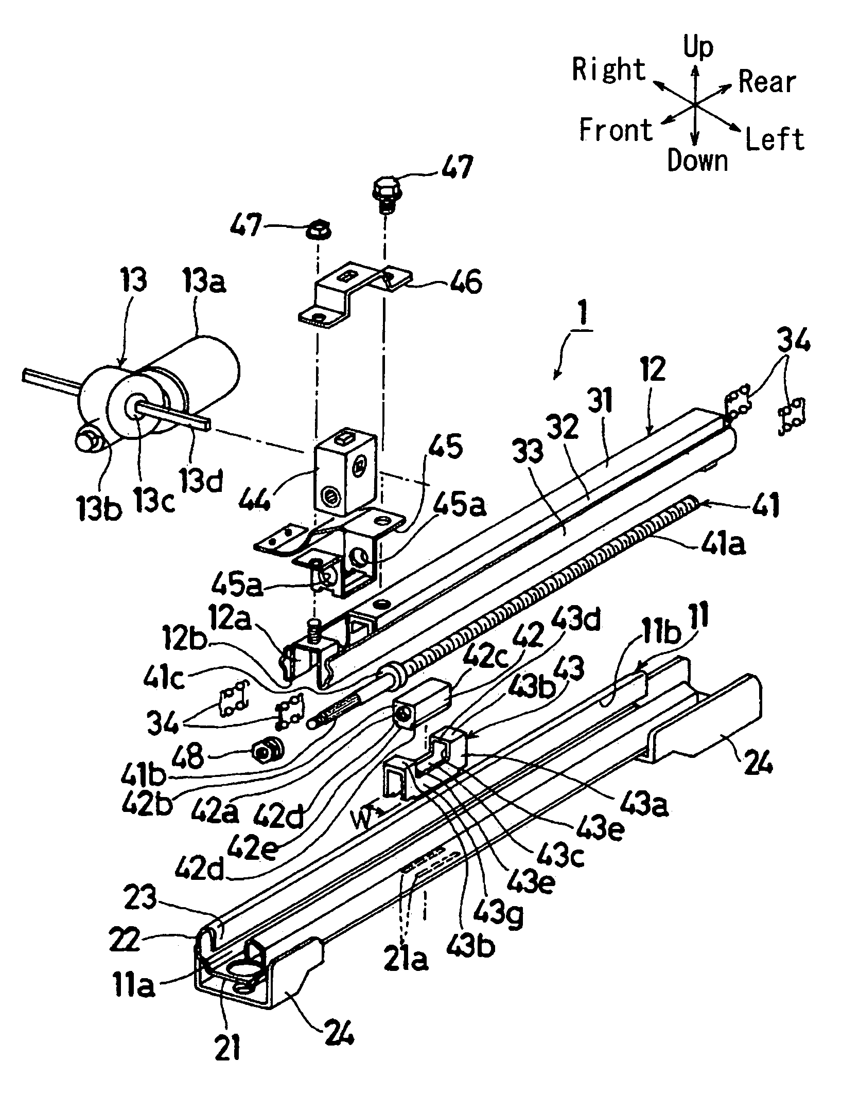
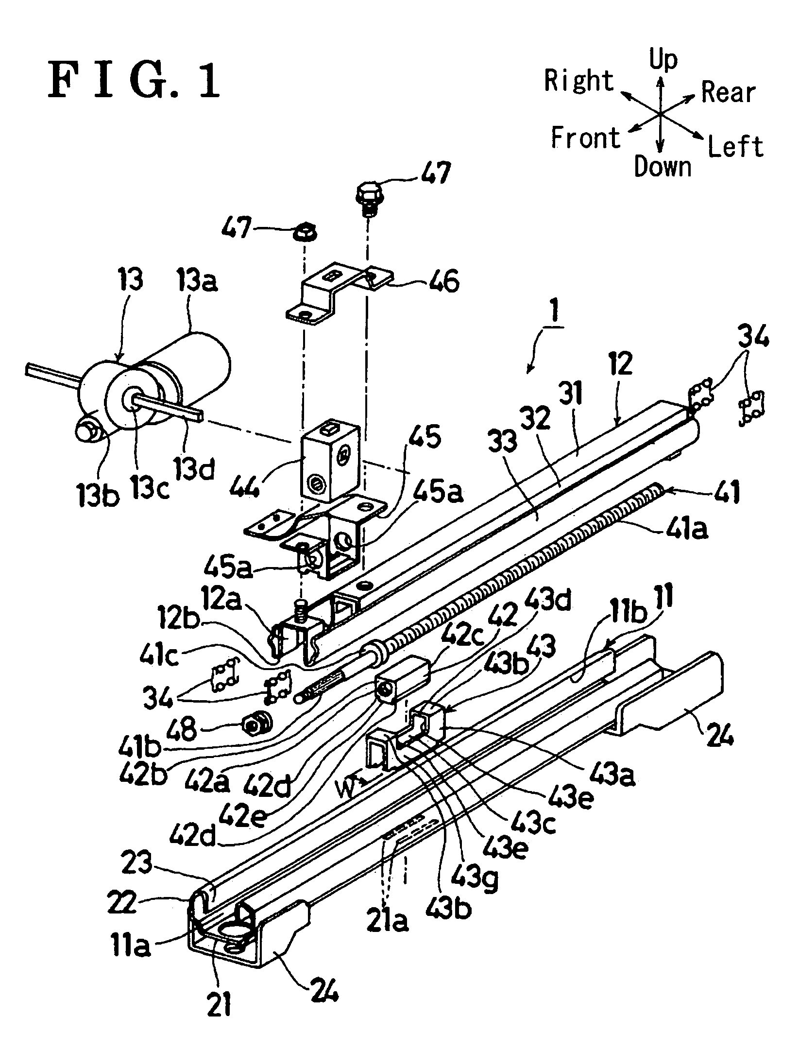
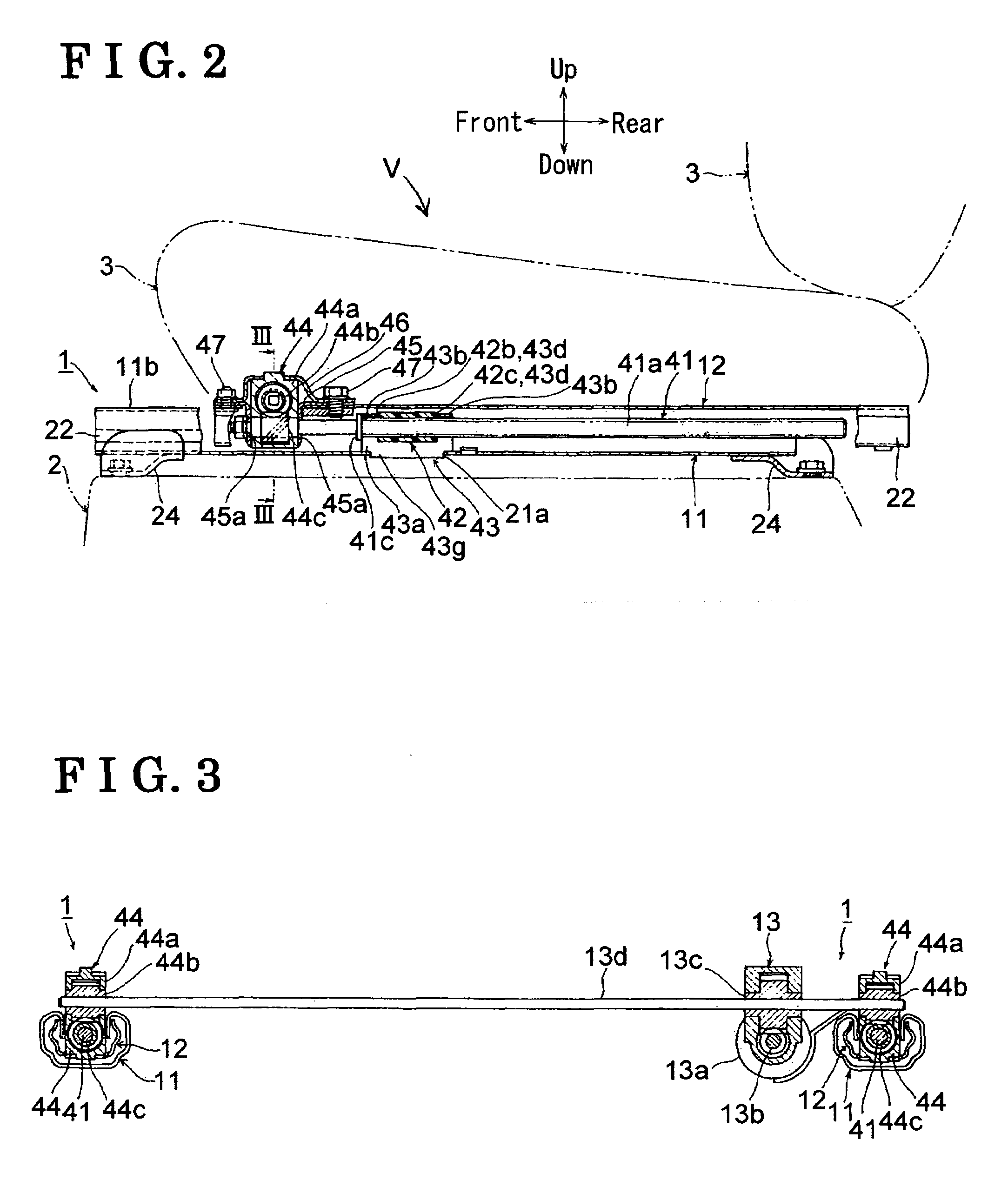
[0022]The power seat slide apparatus 1 according to the first embodiment of the present invention can be preferably mounted, making a lateral pair, on a floor 2 (FIG. 2) of the vehicle V. More particularly, the power seat slide apparatus 1, which is one of the pair, is positioned at a right side under a seat 3 in a lateral direction of the vehicle V, while the power seat slide apparatus 1, which is the other one of the pair, is positioned at a left side under the seat 3. In order to simplify the description and illustration, of the seat slide apparatus 1, FIG. 1 illustrates only one seat slide apparatus 1 which is mounted at the left side under the seat S, and the description will be exhibited only for the seat slide apparatus 1 at the left side of the seat S. It is, however, to be understood that both seat slide apparatus 1 possess the same general configuration and so the description below applied to both seat slide apparatus 1.

[0023]As illustrated in FIG. 1, the power seat slide ...

second embodiment

[0049]According to the first embodiment of the present invention, the portion L1, which is positioned ahead of the notch 43c, possesses substantially the same longitudinal direction as the longitudinal direction of the portion L2, which is positioned behind the notch 43c. However, according to a second embodiment, as illustrated in FIGS. 6 and 7, an extending portion 43h and extending portions 43i are integrally formed with the upper wall 43b and the side walls 43a respectively and extends therefrom to a rear end portion (i.e., one end) of the opening 11b of the lower rail 11. Therefore, a longitudinal area up to the rear end portion of the opening 11b is covered by the extending portions 43h and 43i, which can further improve an appearance of the lower rail 11, can further restrain foreign obstacles from dropping into the internal space 11a, and so on. Alternatively, the extending portions 43h and 43i can extend respectively from the upper wall 43b and the sidewalls 43a to a rear e...

third embodiment

[0052]A single rigid member is employed as the connecting bar 13d according to the first embodiment of the present invention. According to a third embodiment, as illustrated in FIG. 8, the connecting bar 13d is substituted by a structure having an inner cable 13e and an outer tube 13f supporting the inner cable 13e therein. The inner cable 13e is made of twisted steel wires, and the outer tube 13f is made of a resin having flexibility. The outer tube 13f freely slidably supports the inner cable 13e therein.

[0053]According to the aforementioned structure having the inner cable 13e and the outer tube 13f, even if the input gears 44b of the gear units 44 are position at laterally different heights on a floor having a step as illustrated in FIG. 8, driving force of the single driving mechanism 13 can be transmitted easily to the gear units 44 positioned at the both lateral sides.

[0054]The structure of the power seat slide apparatus 1 according to the third embodiment is substantially th...


PUM


Abstract

A power seat slide apparatus includes: a housing fixedly mounted on the first rail and possessing a reverse U-shaped cross section projecting upwardly with an upper wall, which forms an upper surface of the reverse U-shaped cross section, and first and second sidewalls, which forms side surfaces of the reverse U-shaped cross section. The housing further includes a notch defined by a first notch end surface of the upper wall and a second notch end surface of the first and second sidewalls. A nut member is fitted into the notch of the housing, supported inside the housing, and is held tight in the longitudinal direction of the vehicle by the first notch end surface and the second notch end surface. A screw shaft is freely rotatably supported by the second rail and is engaged with the nut member.

Description

CROSS REFERENCE TO RELATED APPLICATIONS[0001]This application is based on and claims priority under 35 U.S.C. §119 with respect to Japanese Patent Application 2005-112669, filed on Apr. 8, 2005, the entire content of which is incorporated herein by reference.FIELD OF THE INVENTION[0002]This invention generally relates to a power seat slide apparatus for a vehicle.BACKGROUND[0003]A known power seat slide apparatus for a vehicle, which is disclosed in for example Japanese Patent No. 2883804, includes a lower rail fixedly mounted on a floor of a vehicle and an upper rail freely slidably supported by the lower rail and supporting a seat of the vehicle. The lower rail has an internal space, which extends in a longitudinal direction of a vehicle, and an opening, which opens or releases an upper portion of the internal space. This power seat slide apparatus further includes a metal-made housing and a resin-made nut member, a screw shaft, and a driving mechanism. The metal-made housing is f...

Claims


Application Information

Patent Timeline
Patent Type & Authority Patents(United States)
IPC IPC(8): B60N2/07B60N2/90
CPCB60N2/067B60N2/0705B60N2/0715B60N2/0735
Inventor ITO, SADAOSAKAI, MAKOTOTSUJI, EIICHIRO
Owner AISIN SEIKI KK
Why Eureka
Try Eureka