Vehicle power seat slide device

a technology of seat slide and power seat, which is applied in the direction of machine supports, movable seats, roofs, etc., can solve the problems of screw shaft bending stress, increased seat slide device cost, and dimensional accuracy degradation

Inactive Publication Date: 2006-08-24
AISIN SEIKI KK
View PDF18 Cites 22 Cited by
  • Summary
  • Abstract
  • Description
  • Claims
  • Application Information

AI Technical Summary

Problems solved by technology

However, if the nut member is not supported by the bracket appropriately, the excessive load at the time of, for example the vehicle collision, transmits from the screw shaft to the gear box, as a result a bending stress may occurs on the screw shaft.
However, these measures result in increasing the costs of the seat slide device, in addition, the welding may result in

Method used


Image

  • Vehicle power seat slide device
  • Vehicle power seat slide device
  • Vehicle power seat slide device

Examples


first embodiment

[0017] (First embodiment)

[0018] A first embodiment of the present invention will be explained in accordance with the attached FIGS. 1 through 3. Specifically, in the first embodiment, a power seat slide device, to which the present invention is applied, is mounted to, for example a front seat of a vehicle. In the first embodiment, a front-rear direction, a right-left direction and an upper-lower direction is defined relative to the vehicle.

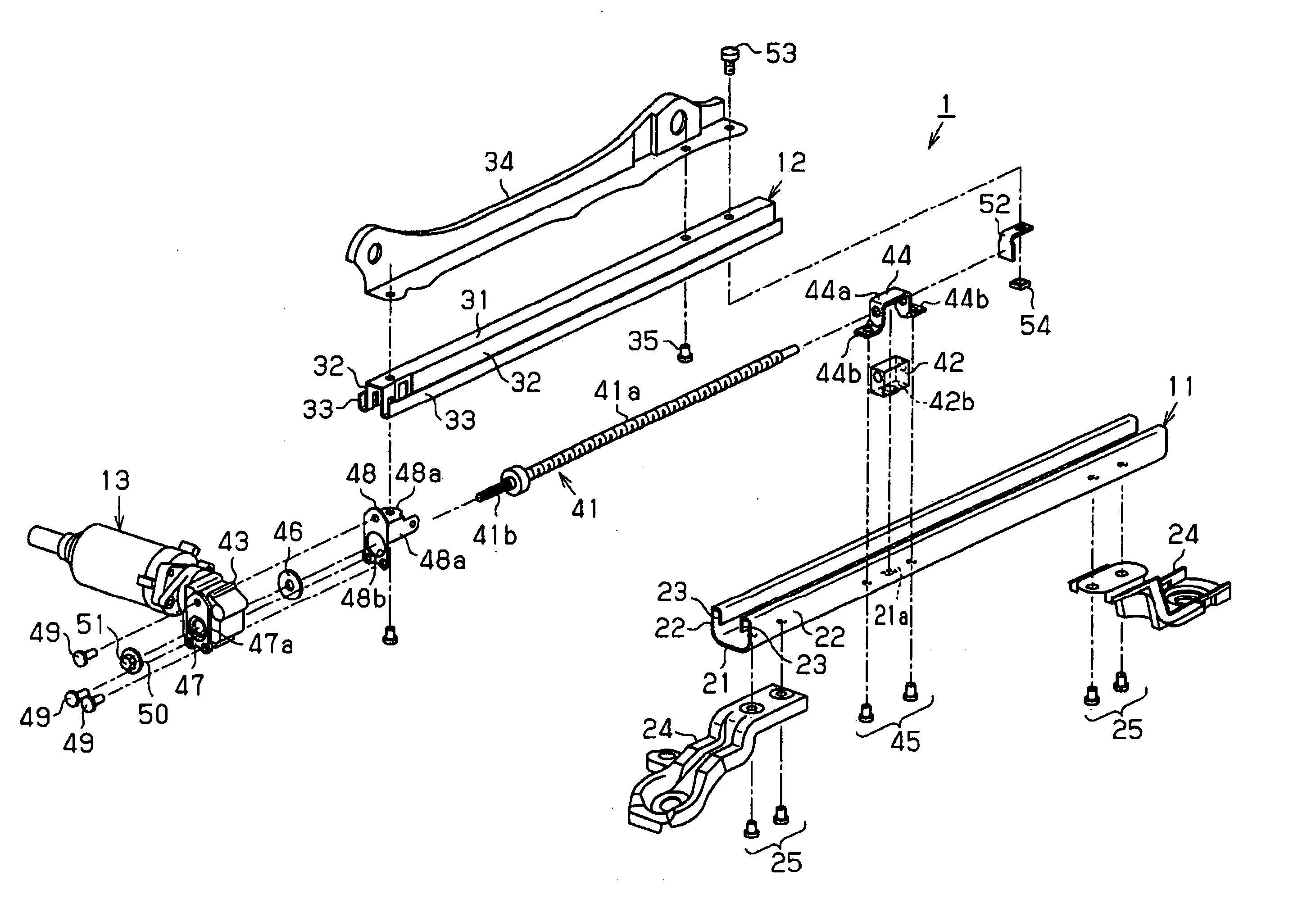
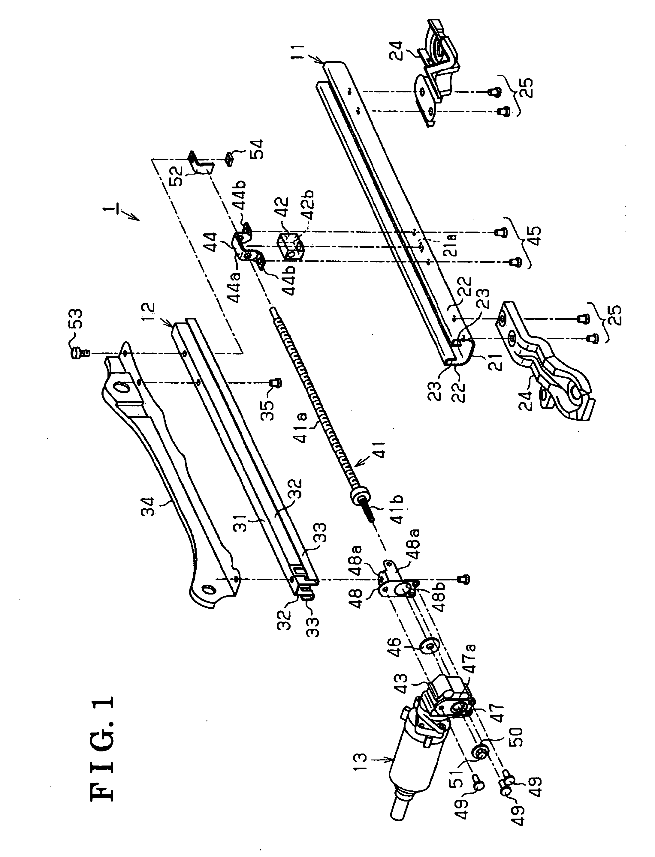
[0019]FIG. 1 illustrates an exploded perspective view of a first embodiment of a power seat slide device. The power seat slide device 1 mainly includes a lower rail 11 (e.g., serving as a first rail), an upper rail 12 (e.g., serving as a second rail) and a driving mechanism 13.

[0020] The lower rail 11 is formed in a long shape so as to extend in a vehicle front-rear direction. Specifically, the lower rail 11 is formed in an approximate U-shaped in its cross section so as to include a bottom portion 21 and a pair of side walls 22, which extends f...

second embodiment

[0035] (Second embodiment)

[0036] Next, a second embodiment of the present invention will be explained in accordance with FIG. 4. Because the second embodiment has basically the same configuration as the first embodiment, only the differences from the first embodiment will be explained.

[0037] The second embodiment basically has a same structure as that of the first embodiment. In the second embodiment, a shape of the nut member 42 differs from that of the first embodiment. In both embodiments, same numerals are applied to the same parts.

[0038] As shown in FIG. 4, a width WI of a protruding portion 61a, which is formed at the nut member 61 is set to be identical to a width W2 of a nut member 61 in a right-left direction. When the width WI of the protruding portion 61a is increased to the width W2 of the nut member 61, an area of a surface at which the protruding portion 61 a is fitted into the fitting hole 21a of the lower rail 11 can be increased. In other words, an area of a surfa...

third embodiment

[0039] (Third embodiment)

[0040] Next, a third embodiment of the present invention will be explained in accordance with FIG. 5. Because the third embodiment has basically the same configuration as the first embodiment, only the differences from the first embodiment will be explained.

[0041] The third embodiment basically has a same structure as that of the first embodiment. In the third embodiment, a reinforcing member 71 is provided to a fitting portion between the protruding portion 42b of the nut member 42 and the fitting hole 21a of the lower rail 11. In both embodiments, same numerals are applied to the same parts.

[0042] As shown in FIG. 5, a height of the reinforcing member 71 is set to be identical to that of the protruding portion 42b of the nut member 42, and a pair of the reinforcing members 71 is provided between the protruding portion 42b and the fitting hole 21a so as to be sandwiched therebetween. Specifically, one of the reinforcing members 71 is provided at front of ...


PUM


Abstract

A vehicle power seat slide device includes a first rail fixed to a vehicle, a second rail fixed to a seat and slidably supported by the first rail, a nut member fixed to the first rail by means of a bracket, a screw shaft rotatably supported by the second rail and screwed into the nut member, a driving mechanism supported by the second rail for driving the screw shaft so as to rotate, the screw shaft being rotated by the driving mechanism relative to the nut member, the second rail being moved so as to slide relative to the first rail by means of the shaft screwing into the nut member, the nut member including a protruding portion fitted into a fitting hole, which is formed on the first rail, the nut member being supported by the bracket, and the bracket fixed to the first rail together with the nut member.

Description

CROSS REFERENCE TO RELATED APPLICATIONS [0001] This application is based on and claims priority under 35 U.S.C. § 119 to Japanese Patent Application 2004-370048, filed on Dec. 21, 2004, the entire content of which is incorporated herein by reference.FIELD OF THE INVENTION [0002] The present invention relates to a vehicle power seat slide device. BACKGROUND [0003] A known power seat slide device disclosed in, for example JP2000-158983A, includes a lower rail fixed to a vehicle floor, an upper rail slidably supported to the lower rail in order to support a vehicle seat, a nut member fixed to the lower rail, a screw shaft screwed into a nut member, which is rotatably supported by the upper rail, and a gear box supported by the upper rail and connected to the screw shaft and the electric driving source. [0004] When the known device rotates the screw shaft relative to the nut member through the gear box by the electric driving source, the screw shaft is screwed into the nut member, and t...

Claims


Application Information

Patent Timeline
IPC IPC(8): B60N2/02
CPCB60N2/0232B60N2/067B60N2/02246
Inventor KIMURA, TOSHIHIRONAKAMURA, YOSHITAKA
Owner AISIN SEIKI KK
Why Eureka
Try Eureka