Method and apparatus for tracing remote ends of networking cables

a network cable and remote end technology, applied in the field of methods and circuits, can solve the problems of additional costs, further service problems, labor intensive and expensive processes, etc., and achieve the effect of facilitating identification

Inactive Publication Date: 2008-02-05
BROWN ALAN J
View PDF14 Cites 31 Cited by
  • Summary
  • Abstract
  • Description
  • Claims
  • Application Information

AI Technical Summary

Problems solved by technology

Tracing and identifying a remote connector section or end of a specific cable for changing its connection in a network or to facilitate replacement often is difficult, tedious and time consuming, and can lead to errors which create further service problems and additional costs.
This process may be labor intensive and expensive.
This process is also labor intensive.
As a result, these methods interfere with performance and require the workstation to be taken out of service.
If the workstation and server are located in separate rooms or in remote locations, the previous methods are labor intensive and inefficient for easy detection of termination ends.

Method used


Image

  • Method and apparatus for tracing remote ends of networking cables
  • Method and apparatus for tracing remote ends of networking cables
  • Method and apparatus for tracing remote ends of networking cables

Examples


Embodiment Construction

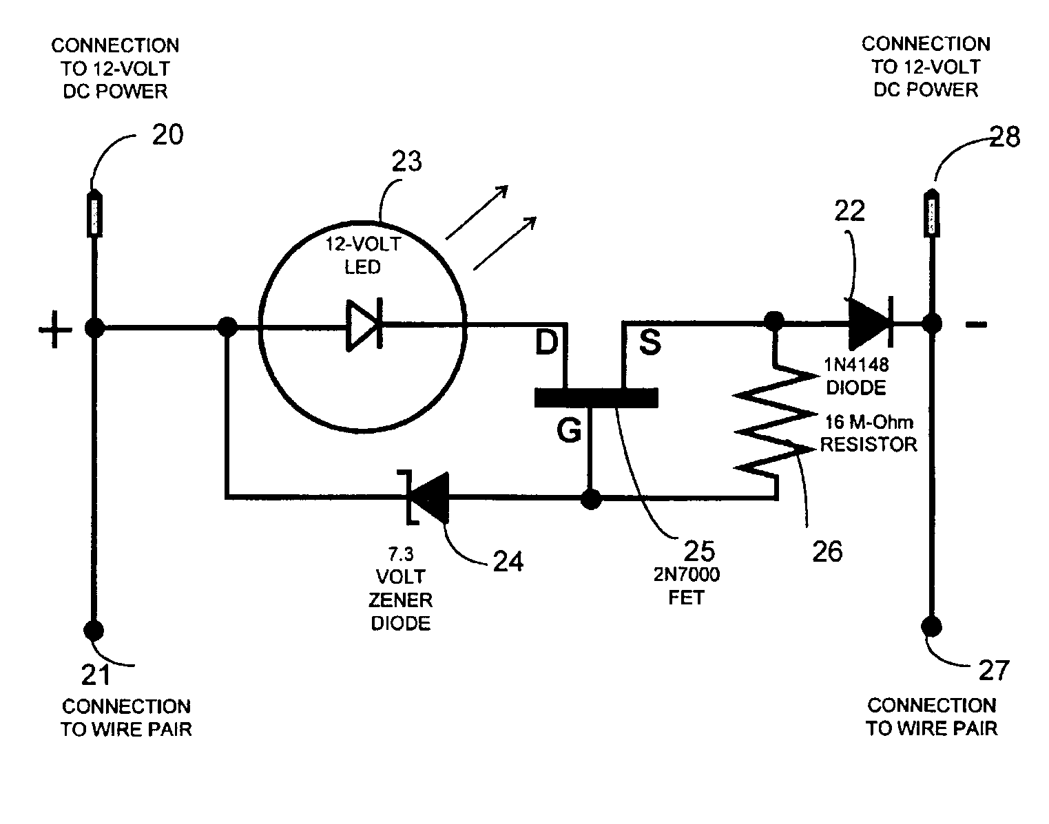
[0030]The present invention relates to a method and a circuit that facilitates identifying a remote end and optionally an intermediate location of an installed cable, such as a cable for carrying data, such as an Ethernet cable, without the need to disconnect the cable. In accordance with one aspect of the present invention, the circuit may be connected across two wires in a cable at one or more locations along its length. Each circuit includes a power connector, a switching circuit and an indicator, such as a light emitting diode (LED). The circuit is configured such that the indicators in all circuits connected across the two wires are illuminated in response to a nominal voltage being applied to a power connector in any of the circuits connected across the two wires without disrupting any data being carried by the two wires.

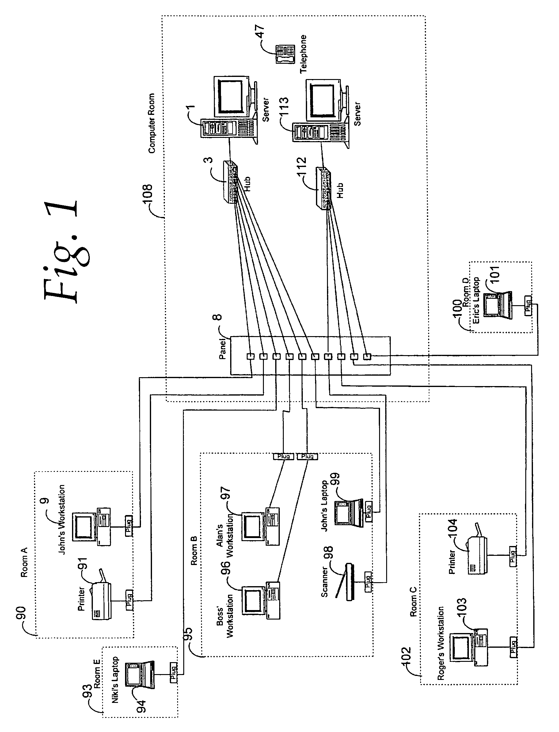
[0031]FIG. 1 illustrates a number of exemplary applications of the circuit in accordance with the present invention. Two embodiments of the circuit in accorda...


PUM


Abstract

A method and a circuit is disclosed that facilitates identifying a remote end and optionally an intermediate location of an installed cable, such as a cable for carrying data, without the need to disconnect the cable. One or more circuits may be connected across two wires along the length of a cable. Each circuit includes a power connector, a switching circuit and an indicator, such as a light emitting diode (LED), connected across the two wires included in a cable. The circuit is configured such that the indicator in each circuit connected to the two wires is illuminated in responsive to a nominal DC voltage applied to the power connector in any circuits connected across the two wires without disrupting any data being carried thereby. In one embodiment of the invention, the circuit is directly into a cable connector. In an alternate embodiment of the invention, the circuit is configured to be retrofit in the field for use with existing cables.

Description

CROSS-REFERENCE TO RELATED APPLICATIONS[0001]The present application is a continuation-in-part of commonly owned application Ser. No. 10 / 360,882, filed on Feb. 7, 2003, now U.S. Pat. No. 6,975,242 which, in turn, is a continuation of application Ser. No. 09 / 460,775, filed on Dec. 14, 1999, now U.S. Pat. No. 6,577,243.BACKGROUND OF THE INVENTION[0002]1. Field of the Invention[0003]The present invention relates to a method and a circuit that facilitates identifying a remote end and optionally an intermediate location of an installed cable, such as a cable for carrying data, without the need to disconnect the cable and includes a circuit at one or more locations along the cable; the circuit including a power connector, a switching circuit and an indicator, such as a light emitting diode (LED), connected across a two wires in a cable for carrying data; the circuit being configured such that the indicator in each circuit is illuminated in response to a nominal voltage being applied to th...

Claims


Application Information

Patent Timeline
Patent Type & Authority Patents(United States)
IPC IPC(8): G09F9/33G01R19/00
CPCG01R31/041H01R13/465H01R13/717H01R13/7175H01R29/00H01R24/64G01R31/67
Inventor DANNENMANN, JOHNHELGERSON, RONALD
Owner BROWN ALAN J
Why Eureka
Try Eureka