Heater assembly for a respiratory treatment machine

a technology of respiratory treatment machine and heating plate, which is applied in the field of heating plate, can solve the problems of user being easily hurt by the high and the user being easily hurt by the temperature of the heating pla

Active Publication Date: 2008-02-05
APEX MEDICAL CORPORATION
View PDF3 Cites 43 Cited by
  • Summary
  • Abstract
  • Description
  • Claims
  • Application Information

AI Technical Summary

Benefits of technology

[0008]In order to accomplish the objective of the present invention, the heating assembly of the present invention has a base and a water tank. The base is provided with a recessed platform, a receiving space defined inside the base and communicating with the platform via an opening of the receiving space and a heating plate placed on a bottom face of the receiving space. A protection gate is pivotally mounted at a side face of the opening of the receiving space. The water tank is provided with a secondary receptacle extending outward from and communicating with the water tank. A conducting plate is provided at a bottom face of the water tank and an extension integrally formed with the conducting plate is provided at a bottom face of the secondary receptacle. Therefore, after the secondary receptacle is received in the receiving space, the engagement between the heating plate and the extension of the water tank allows the temperature of the heating plate to be conducted to the extension as well as the conducting plate such that the water inside the water tank is heated. The provision of the protection gate prevents accidental touch to the heating plate such that the user is protected.

Problems solved by technology

Therefore, if the controlling knob (11) is accidentally turned on and the temperature of the heating plate (100) starts to rise, the user may be easily hurt by the high temperature of the heating plate (100).
Even after the heating process is finished and the controlling knob (11) is not turned off, the user may still easily be hurt by the temperature of the heating plate (100).

Method used


Image

  • Heater assembly for a respiratory treatment machine
  • Heater assembly for a respiratory treatment machine
  • Heater assembly for a respiratory treatment machine

Examples


Embodiment Construction

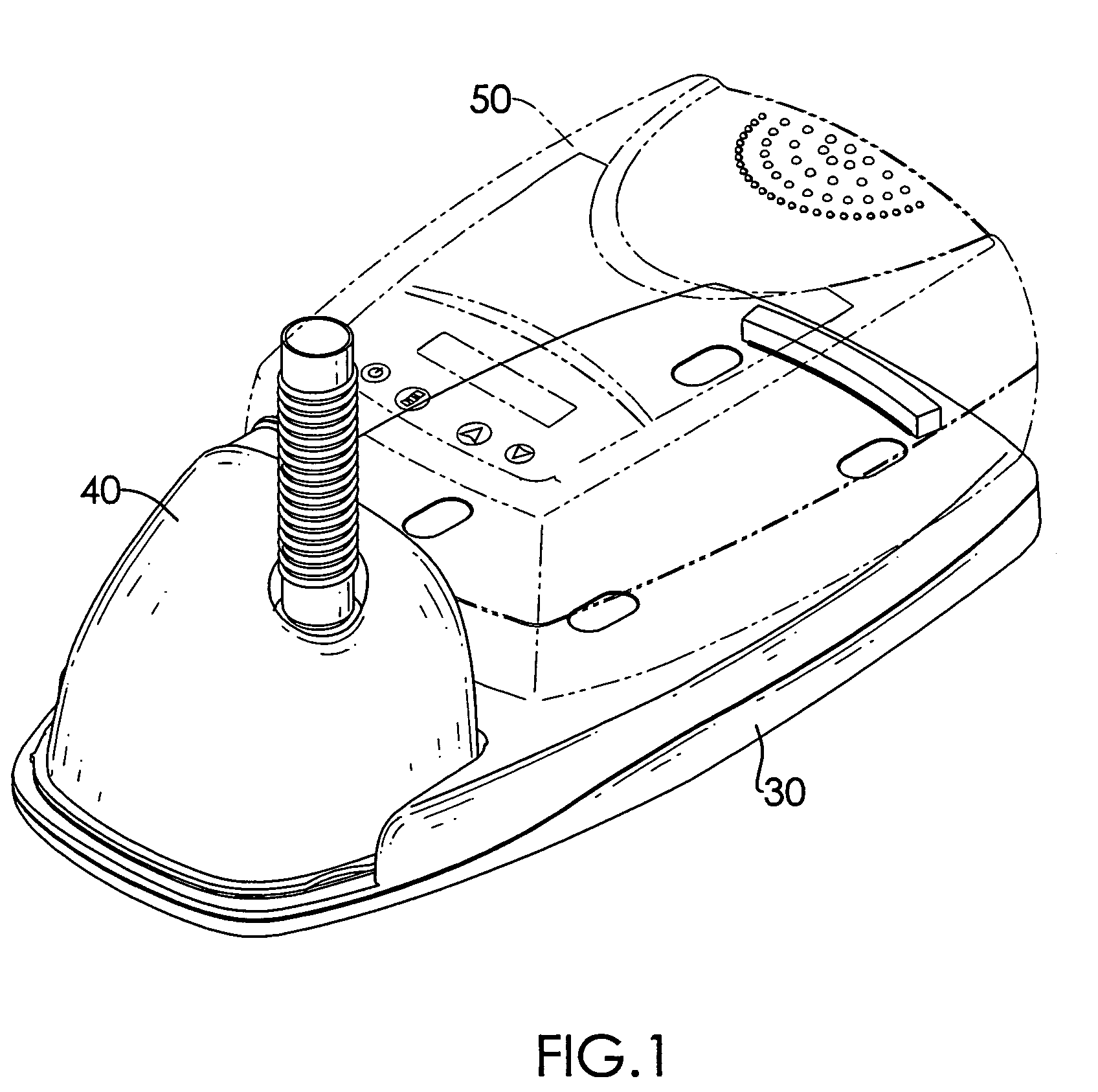
[0020]With reference to FIG. 1, it is noted that the heating assembly in accordance with the present invention normally is associated with a respiratory treatment machine (50). However, because the respiratory treatment machine (50) is not the focus of the present invention, the function and the structure thereof is omitted for clarity and brevity. It is noted that the heating assembly of the present invention is composed of a base (30) and a water tank (40).

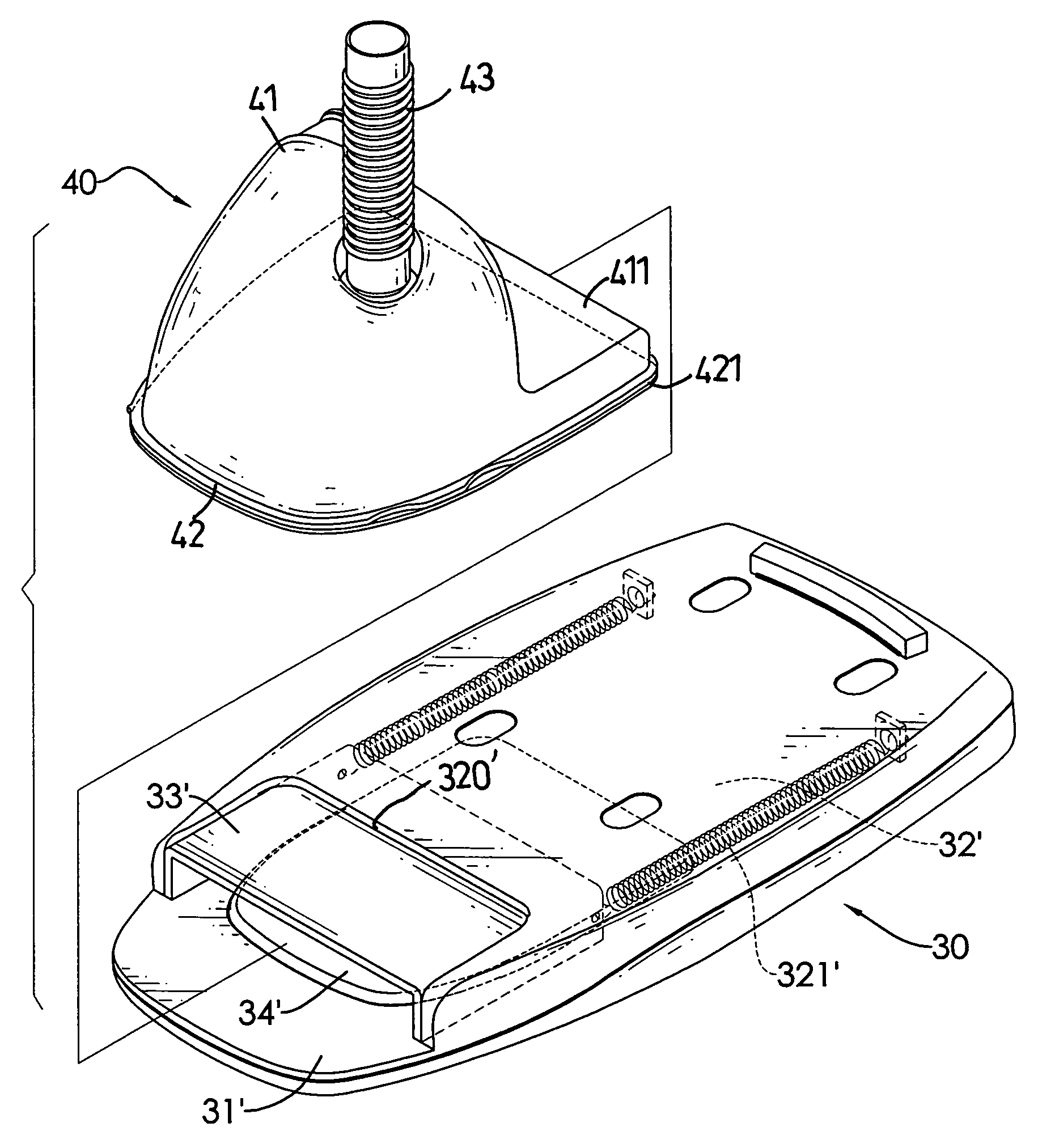
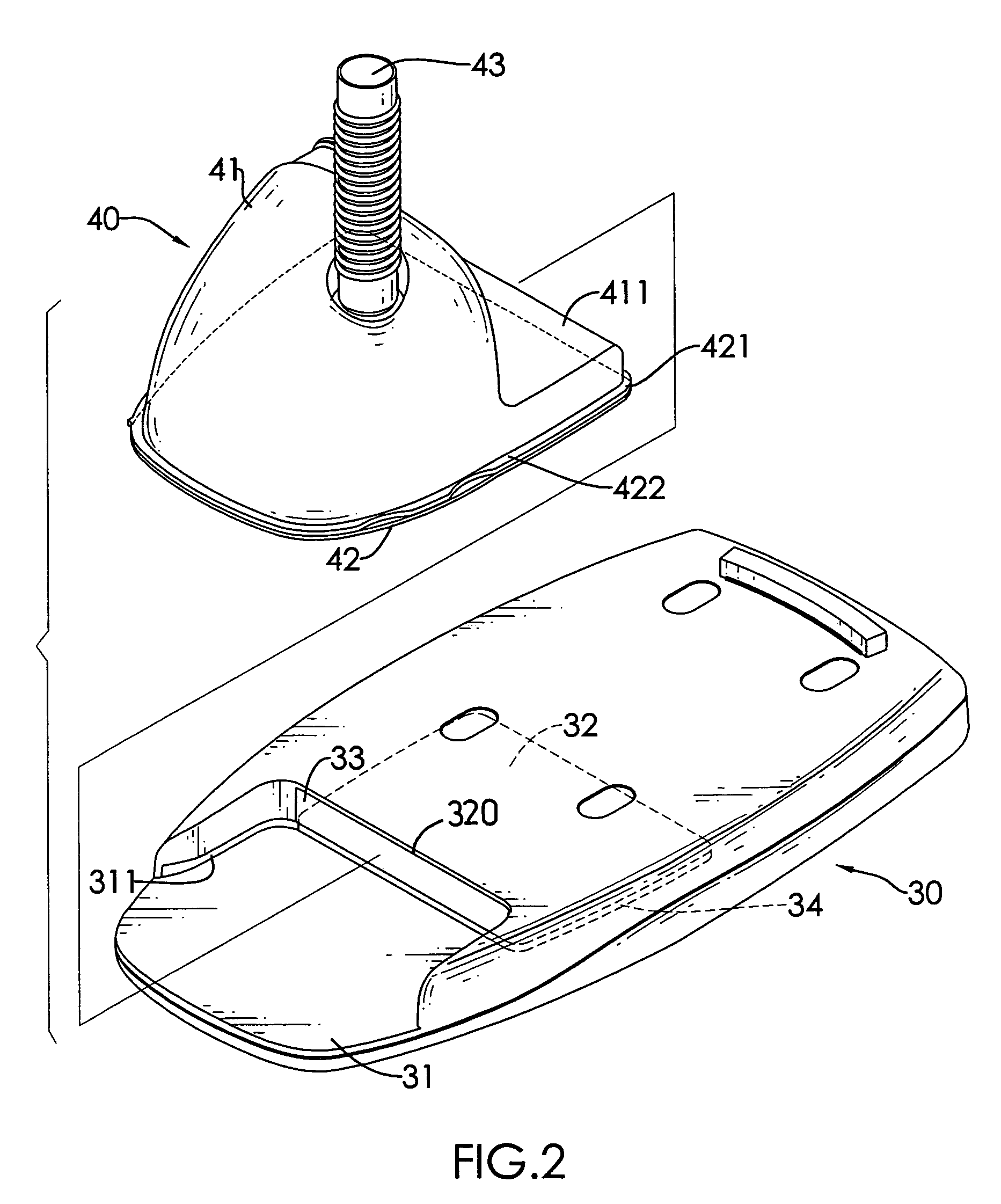
[0021]With reference to FIG. 2, the base (30) includes a recessed platform (31) formed at a front side of the base (30), a receiving space (32) defined inside the base (30) to communicate with the platform (31) via an opening (320), a protection gate (33) pivotally mounted at a side face defining the opening (320) and a heating plate (34) securely placed on a bottom face of the receiving space (32). A guiding track (311) is defined in two opposite sides of the platform (31).

[0022]The water tank (40) has a main receptacle (41) an...


PUM


Abstract

A heating assembly for a respiratory treatment machine includes a base and a water tank. The base has a receiving space communicating with a recessed platform at a via an opening, and a heating plate securely placed on a bottom face of the receiving space. The water tank has a main receptacle, a secondary receptacle integrally formed and communicating with the main receptacle and movably received inside the receiving space, a conducting plate securely provided at a bottom face of the main receptacle and an extension integrally formed with the conducting plate and provided at a bottom face of the secondary receptacle. The extension has a dimension corresponding to that of the heating plate such that after the secondary receptacle is received inside the receiving space, the extension is placed on top of the heating plate and engaged with the heating plate.

Description

BACKGROUND OF THE INVENTION[0001]1. Field of the Invention[0002]The present invention relates to a heater assembly, and more particularly to a heater assembly for a respiratory treatment machine.[0003]2. Description of the Prior Art[0004]A respiratory treatment machine, as shown in FIGS. 7 and 8, includes a base (10) and a water tank (20). The base (10) has a heating plate (100) mounted on a side face of a recessed platform (101) which is defined in a front side of the base (10). A controlling knob (11) is provided on a side of the base (10). The water tank (20) has a heat conducting plate (21) formed at a bottom side of the water tank (20) and corresponding to the heating plate (100). The water tank (20) is designed to receive therein water such that after the water tank (20) is placed on top of the heating plate (100) and the controlling knob (11) is turned on, temperature of the heating plate (100) gradually turns the water inside the water tank (20) into vapor. Then the user is ...

Claims


Application Information

Patent Timeline
Patent Type & Authority Patents(United States)
IPC IPC(8): F24H1/18
CPCA61M16/1075A61M16/109A61M16/16
Inventor CHENG, YAO-MINGLAI, KUNG-KUANHUANG, CHUN-WEI
Owner APEX MEDICAL CORPORATION
Why Eureka
Try Eureka