Femoral compression device

a compression device and femoral artery technology, applied in the field of femoral artery compression device, can solve the problems of inability to determine whether the air cushion has reached its maximum expansion state, no more compression of the femoral artery is possible, and even more pronounced problems, so as to reduce the risk of injury, and reduce the effect of patient movemen

Inactive Publication Date: 2008-02-12
ST JUDE MEDICAL COORDINATION CENT
View PDF17 Cites 44 Cited by
  • Summary
  • Abstract
  • Description
  • Claims
  • Application Information

AI Technical Summary

Benefits of technology

The present invention provides a femoral compression device with a pressurizing means that has a large internal resilience, making it less sensitive to patient movements. This device ensures a direct proportionality between the force applied on the puncture site and the energy loaded into the spring, which reaches its maximum when the spring is completely compressed. The device also includes a gauge that displays the compression pressure being applied on the puncture site. This spring-loaded pressurizing means compensates for differences in the distance between the base plate and the femoral artery, providing a more stable and reliable compression.

Problems solved by technology

The present invention addresses the problem of determining when the inflatable air cushion has reached its maximum expansion and can no longer compress the femoral artery any further, which can occur for patients with a thick layer of adipose tissue. Additionally, the invention addresses the issue of the air cushion losing its compression pressure when the patient moves, resulting in a reduced level of compression.

Method used


Image

  • Femoral compression device
  • Femoral compression device
  • Femoral compression device

Examples


Embodiment Construction

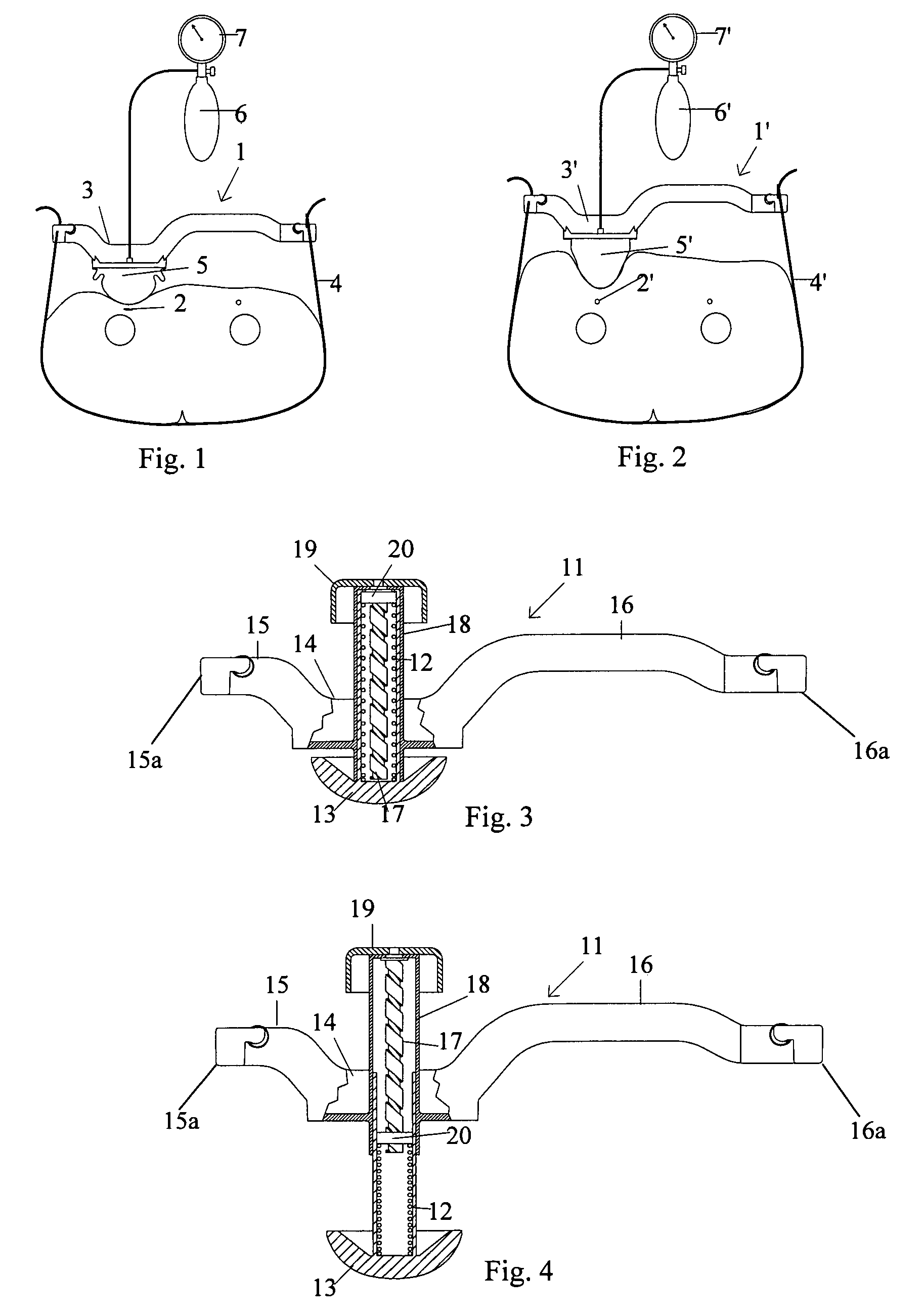
[0018]FIG. 1 illustrates how a previously proposed femoral compression device 1 is attached to the body of a patient in order to apply compression pressure on a femoral artery 2 in which a puncture hole has been made. The compression device 1 comprises basically a base plate 3, a belt 4 and an inflatable air cushion 5, which can be inflated by a pump 6, which is provided with a pressure gauge 7.

[0019]The patient illustrated in FIG. 1 has a normal body constitution, with an average amount of adipose tissue being localised between the skin and the femoral artery 2. When in a semi-inflated state, i.e. less than fully expanded, the air cushion 5 can therefore compress the artery 2 such that no blood penetrates through the puncture hole in the femoral artery 2. Herein, the expression “normal body constitution” refers to a body constitution to which this existing femoral compression device 1 is adapted, i.e. the length of stroke (the expansion) of the air cushion 5 is sufficient for the p...


PUM


Abstract

The invention provides a femoral compression device (11; 21) for compressing a femoral artery of a patient. The femoral compression device (11; 21) comprises a pressurizing means (12; 22), a compression plate (13; 23) for compressive bearing against a puncture site, a base portion (14; 24) provided with two opposing extensions (15, 16; 25, 26), to the ends of which a belt, which is adapted to be arranged around the patient's body, can be fixed. According to the invention, the pressurizing means is in the form of a spring (12; 22), such as a coil spring (12; 22), the first end of which is connected to the compression plate (13; 23) and the second end of which is operatively connected to a handle (19; 29), which can be operated to adjusting the compression of the spring (12; 22).

Description


Claims


Application Information

Patent Timeline
Owner ST JUDE MEDICAL COORDINATION CENT
Why Eureka
Try Eureka