Retractable writing material

a writing tool and retractable technology, applied in the field of retractablenib writing tools, can solve the problems of insufficient sealing and adversely affecting the sealing performance, and achieve the effect of preventing the writing body from drying

Inactive Publication Date: 2008-02-19
PENTEL KK
View PDF7 Cites 23 Cited by
  • Summary
  • Abstract
  • Description
  • Claims
  • Application Information

AI Technical Summary

Benefits of technology

[0005]An object of the present invention is to provide a retractable-nib writing tool capable, when the writing body is retracted, of securely sealing the writing nib at the tip by the combination of the sealing lid and the sealing tube and thereby preventing the writing body from drying.
[0008]In the retractable-nib writing tool, it is possible to provide means of regulating the forward motion of at least one thin line portion out of the plurality of thin line portions which are advanced by the forward motion of the guide tube.
[0009]In the retractable-nib writing tool, it is possible to regulate the forward motion of at least one thin line portion out of the plurality of thin line portions which are advanced by the forward motion of the guide tube and to structure other thin line portions to be bendable and deformable.

Problems solved by technology

However, since the sealing lid is linked to the sealing tube by a hinge in the cap-less writing tool mentioned above, not only the sealing will be insufficient where the elastic force of the springy member is too small but also, even if the elastic force is large, the sealing may still be insufficient.
In other words, since the direction of the force which presses the sealing lid toward the sealing tube is not in parallel to the longer axis of the writing tool, strong pulling would make the balance disturbed by the tension of the string-shaped member and the extension of the hinge to adversely affect the sealing performance.

Method used


Image

  • Retractable writing material
  • Retractable writing material
  • Retractable writing material

Examples


first embodiment

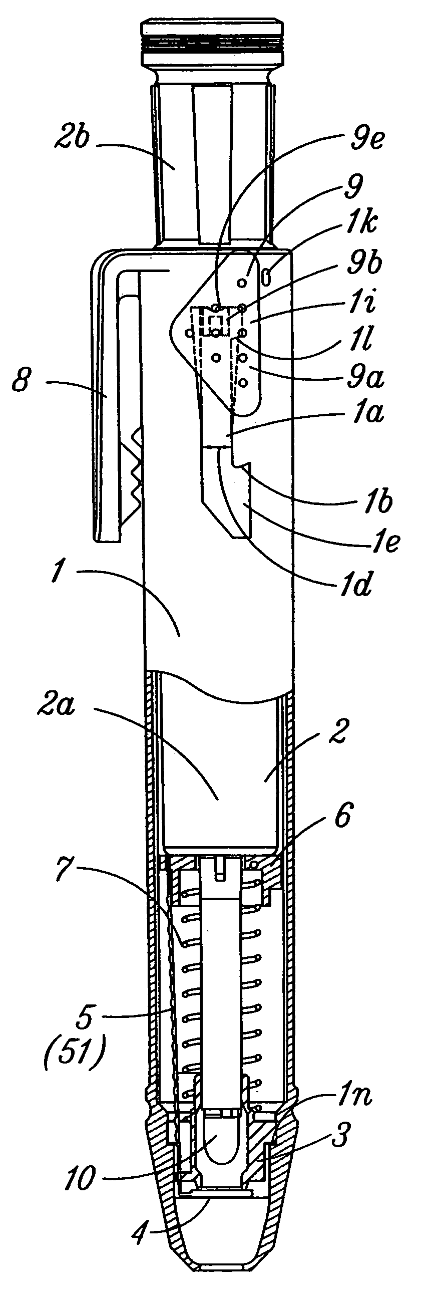
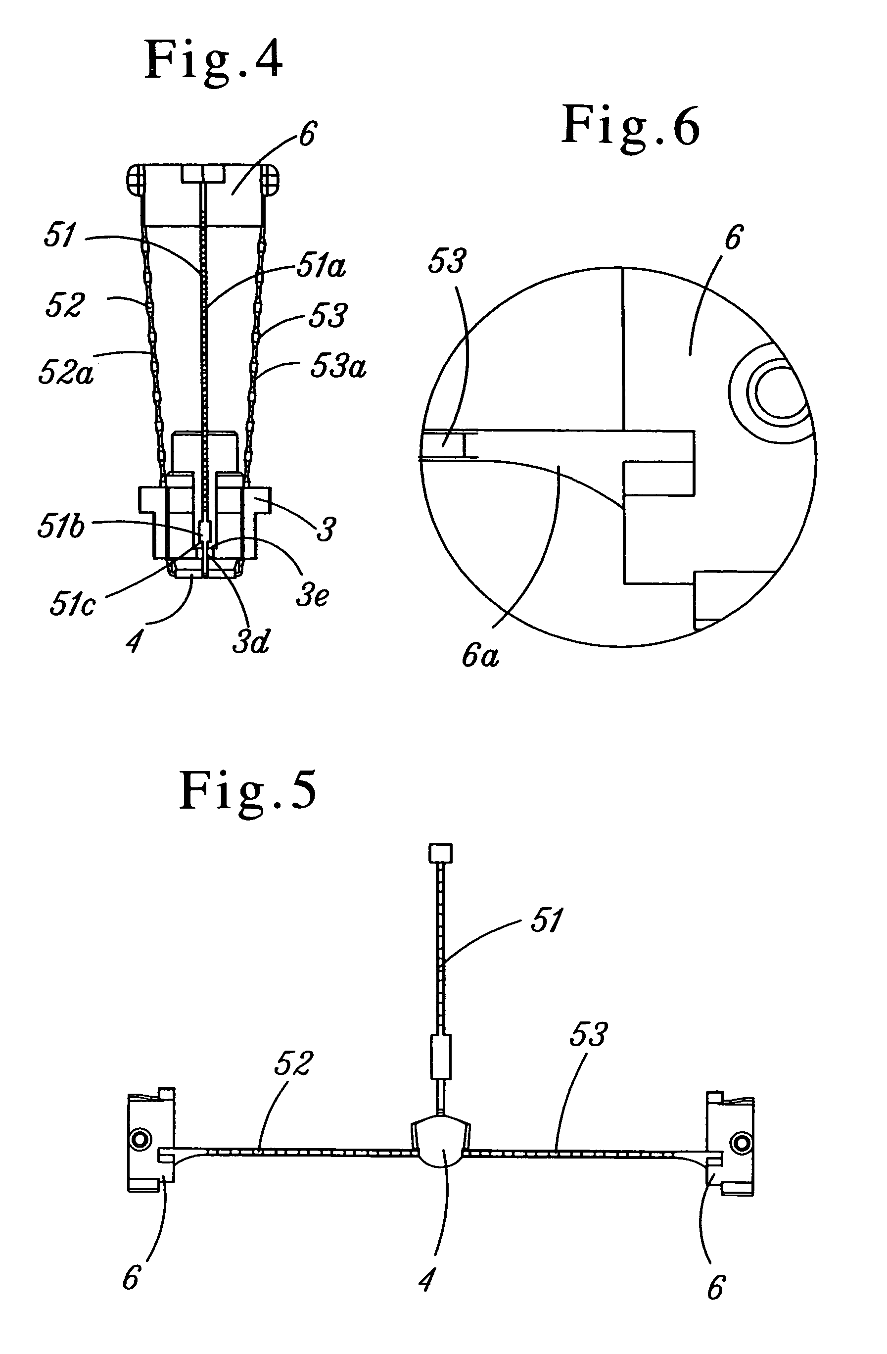
[0042]A first preferred embodiment of the present invention will be described with reference to FIG. 1 through FIG. 10. FIG. 1 is a partial longitudinal section showing a state in which a writing body 2 is retracted, i.e., a state in which a sealing lid 4 is sealed. A sealing tube 3 urged forward by a springy or resilient member 7 is set in the forward part within a tubular member or shaft tube 1, and the sealing tube 3 is prevented from coming off the shaft tube 1 by the engagement of its forward end with a stepped portion 1n, but the sealing tube 3 may as well be formed integrally with the inner face of the shaft tube 1. Inner ribs 3a for keeping sealed closure with the forward outer wall of the writing body 2 are formed on the rear inner face of the sealing tube 3 as shown in FIG. 7. Whereas three flexible elongate members in the form of thin line portions 51, 52 and 53 are formed radially from the sealing lid 4 and at equal intervals (120 degree intervals) in a unitary structure...

second embodiment

[0061]A second preferred embodiment of the invention is shown in FIG. 12 through FIG. 15. The plurality of flexible elongate members in the form of thin line portions 51, 52 and 53 are formed integrally with the sealing lid 4 as in the first embodiment. However, though the rear ends of two thin line portions 52 and 53 are fixed to the guide tube 6, the other thin line portion 51 is loosely inserted into a guide through groove 6c(or a through hole) provided in an outer side of the guide tube 6, and not so many contracted diameter portions are formed as in the foregoing first embodiment. Also, an engaging step portion 51e is disposed near the rear end of the thin line portion 51 as shown in FIG. 14, and the engaging step portion 51e is to be engaged with the through groove 6c. Thus, when the writing body 2 is retracted, as the engaging step portion 51e is engaged with an engaging step portion 6b disposed near the through groove 6c on the outer face of the guide tube 6, together with t...

example of experiment

[0072]The retractable-nib writing tool described above was subjected to measurement of the sealing force and evaluation of its durability over time.

[0073]

[0074]In the state shown in FIG. 1, the knocking member 2b is removed from the writing body 2, and a silicon tube is linked to the rear end of the writing body 2 in a sealed state (not shown). The other end of the silicon tube is linked in a sealed state to a leak tester (product of Tokyo Seimitsu Co., Ltd.). The shaft tube 1 on the sealing tube 3 side is about half soaked in a suitable vessel. In this state, air pressure of a desired level is supplied from the leak tester for 12 seconds, and the limit value of air pressure where no bubble is generated from the sealed part between the sealing tube 3 and the sealing lid 4 or from the sealed part between the forward outer wall part of the writing body 2 and the inner ribs 3a is determined to represent the sealing force.

[0075]

[0076]In the state shown in FIG. 1, an ink absorbent (acryl...


PUM


Abstract

This is a retractable-nib writing tool having a retractable writing body in a shaft tube and having a sealing lid and a sealing tube which seal the writing nib of the writing body in association with the forward and backward movements of the writing body. In this retractable-nib writing tool, the sealing lid and a guide tube fixed to the writing body are linked by a plurality of thin line portions, the sealing lid and thin line portions are formed integrally, and the sealing lid is opened and closed relative to the sealing tube by the forward and backward movements of those thin line portions. This retractable-nib writing tool can securely seal, when the writing body is retracted, the writing nib at the tip by the sealing lid and the sealing tube and thereby prevent the writing body from drying.

Description

CROSS-REFERENCE TO RELATED APPLICATIONS[0001]This application is a U.S. national stage application of copending International Application No. PCT / JP2003 / 014355, filed Nov. 12, 2003, claiming priority dates of Nov. 18, 2002; May 29, 2003; and Aug. 27, 2003, and published in a non-English language.TECHNICAL FIELD[0002]The present invention relates to a retractable-nib writing tool having a retractable writing body in a shaft tube and a sealing lid and a sealing tube for sealing the writing nib of the writing body in association with the forward and backward movements of the writing body.BACKGROUND ART[0003]Known conventional retractable-nib writing tools include, for instance, a cap-less writing tool described in Japanese Patent Publication No. 5-68360. In this cap-less writing tool, a sealing tube having a through hole through which a writing nib at the tip of a writing body is provided within the body, a sealing lid is swingably fitted near the tip hole of this sealing tube and, whe...

Claims


Application Information

Patent Timeline
Patent Type & Authority Patents(United States)
IPC IPC(8): B43K5/16B43K24/02B43K7/12B43K5/17B43K8/02B43K24/04B43K24/08
CPCB43K5/17B43K24/084B43K24/04B43K8/028B43K24/02B43K24/08
Inventor FUKUI, HISAOFURUICHI, AKINORIMIYASHITA, YASUSHI
Owner PENTEL KK
Why Eureka
Try Eureka