Optical sensor

a technology of optical sensors and optical sensors, applied in the field of optical sensors, can solve the problems of unfavorable increase in production costs, and achieve the effect of a particularly cost-effective and economical production of optical sensors

Inactive Publication Date: 2005-09-15
LEUZE ELECTRONICSLEUZE ELECTRONICS GMBH & CO KG
View PDF11 Cites 23 Cited by
  • Summary
  • Abstract
  • Description
  • Claims
  • Application Information

AI Technical Summary

Benefits of technology

[0007] It is the object of the present invention to provide an optical sensor of the aforementioned type which can be produced economically, and which has improved mechanical characteristics.
[0011] The number of parts required for producing an optical sensor and, at the same time, the production time are considerably lower, which results in a considerable reduction in costs for producing the optical sensor.
[0012] Also advantageous is the low melting point for the low-pressure injection molding operations, used to produce parts made from low-pressure injection molding compound. Affixing parts of this type to the sensor casing, which is composed of metal or plastic materials with noticeably higher melting points, can therefore be realized without impairment or damage. Polyamide is particularly suitable as a low-pressure injection molding compound.
[0013] The parts made from low-pressure injection molding compound can be attached in various forms to the casing or to other elements connected to the casing and / or can be secured in position thereon. The parts of low-pressure injection molding compound can simultaneously function as position-fixing means and sealing means. The position-fixing and sealing means formed in this way can be produced by means of a low-pressure injection molding operation, thereby considerably reducing the number of parts required for the optical sensor, as well as the time required for assembling the optical sensor.
[0014] According to a particularly advantageous embodiment of the invention, the optical sensor according to the invention is provided with a lid for closing off the casing body. The mechanical design of the casing body is such that when fitting the lid onto the casing body, a closed low-pressure injection molding channel is formed which extends in circumferential direction along the joining locations between lid and casing body and additionally extends to the electrical connecting means in the form of a connector or cable. A single low-pressure injection molding operation, with injection molding compound inserted into the low-pressure injection molding channel, is thus sufficient to seal in and secure in position the lid and connecting means on the casing body. A particularly economical and cost-effective production of the optical sensor is thus possible, which furthermore provides a uniform and reliable seal owing to the low-pressure injection molding compound, even for large parts such as lids and the like.
[0017] Finally, the optical sensor casing itself can consist of low-pressure injection molding compound. In that case, the optical and electronic components of the optical sensor form an assembly unit which is completely encased by the injection molding compound in order to form a basic casing body. This variation also permits a particularly cost-effective and economical production of the optical sensor.

Problems solved by technology

These additional production processes considerably increase the time required for producing the optical sensor and thus lead to an undesirable increase in the production costs.
Apart from that, problems occur with sealing means of this type, especially if relatively large areas must be sealed, because irregularities during the application of the sealing means result in leaks which allow humidity or dirt to enter the sensor inside space.

Method used


Image

  • Optical sensor
  • Optical sensor
  • Optical sensor

Examples


Embodiment Construction

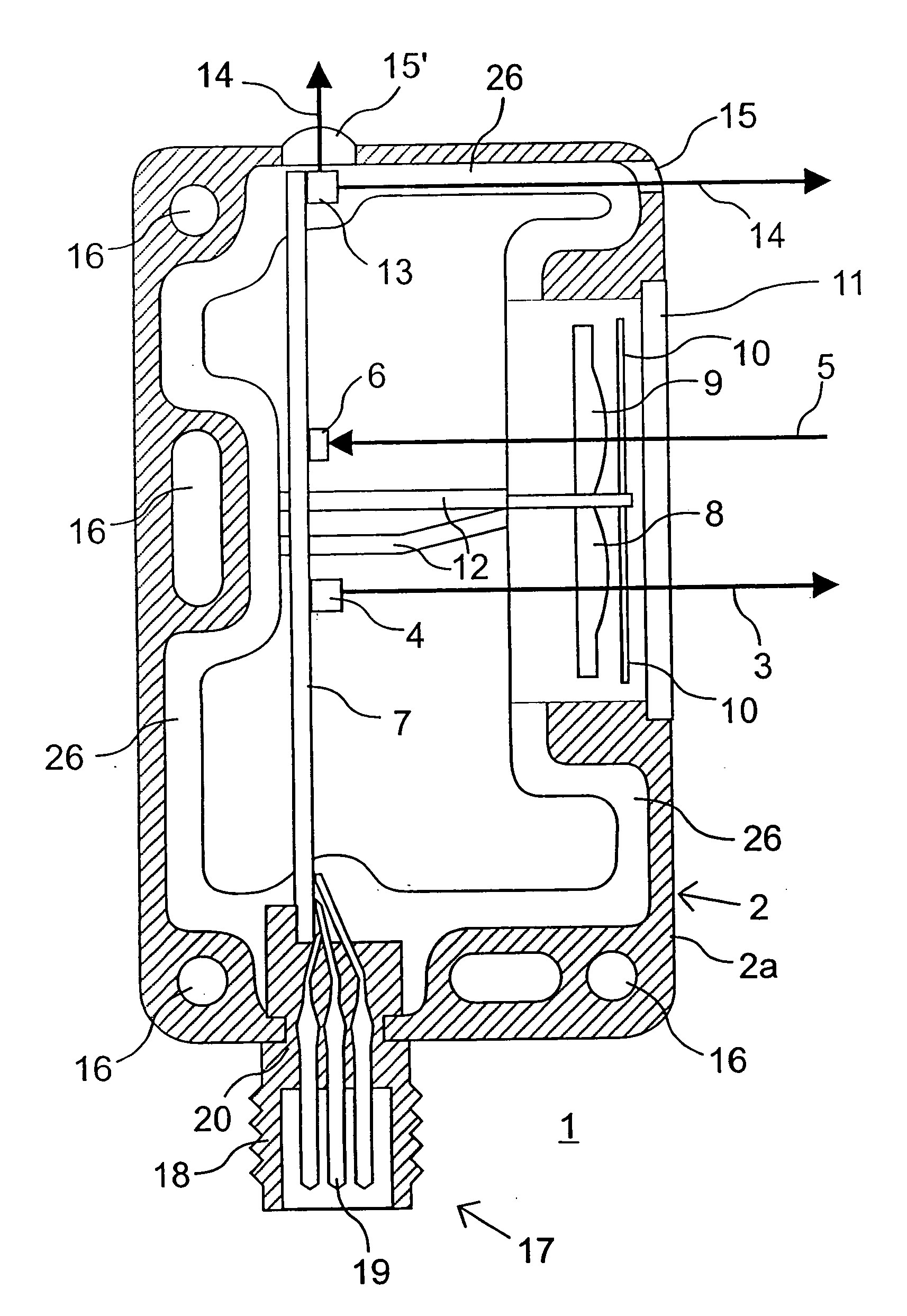
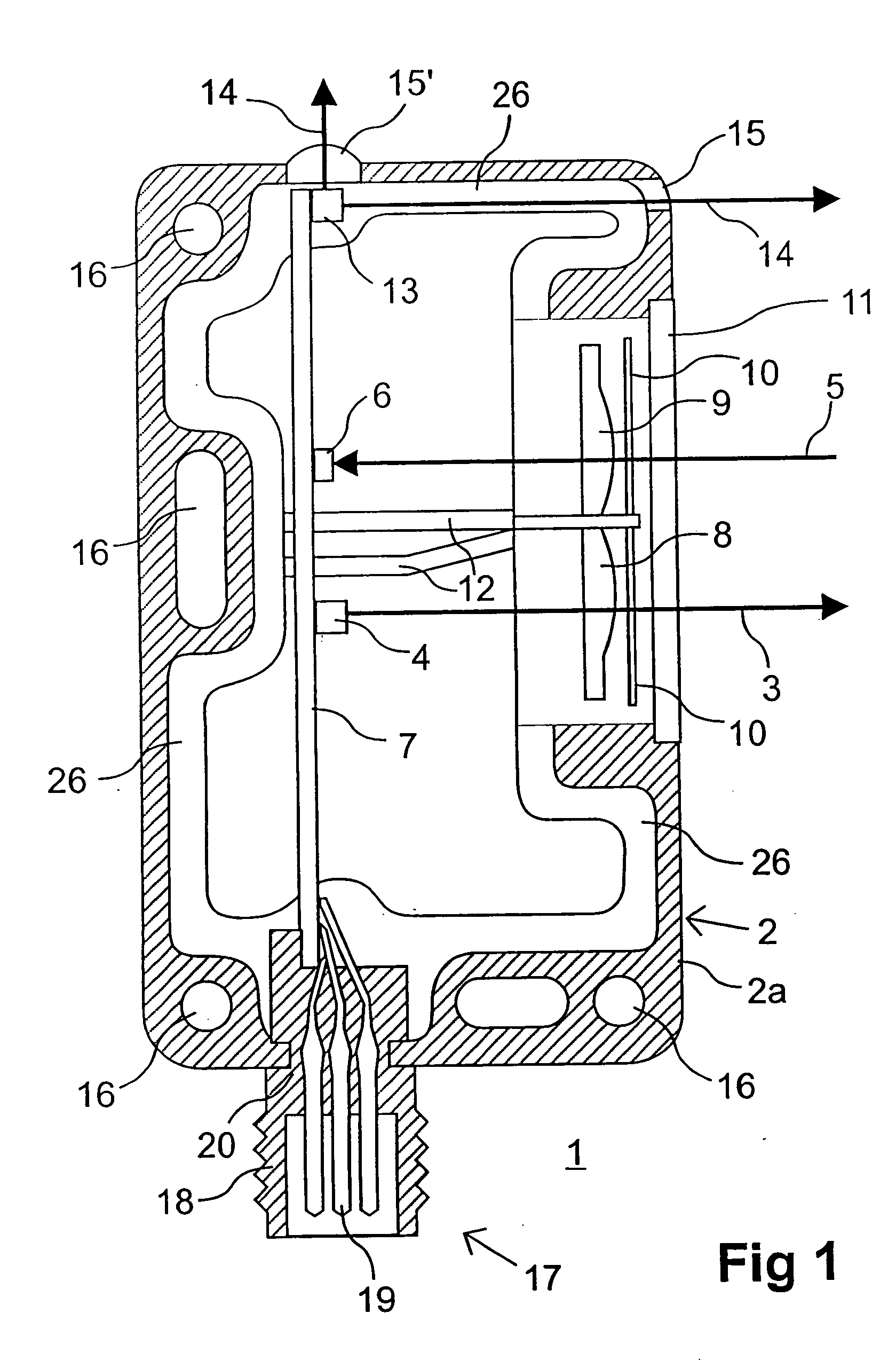
[0027]FIG. 1 shows a first exemplary embodiment of an optical sensor 1 for detecting objects in an area to be monitored, wherein the optical sensor 1 herein is embodied as light scanner 7. However, the optical sensor 1 can, in principle, also be embodied as a light barrier, reflection light barrier, distance-measuring sensor or the like.

[0028] The optical sensor 1 is provided with a casing 2 of metal or plastic for accommodating optical and electronic components. FIG. 1 shows the casing body 2a which can be closed off with a lid 2b, wherein the lid is shown in FIGS. 3a,b. For object detection, the optical sensor 1 is provided with a transmitter 4 that emits light rays 3 and a receiver 6 that receives light rays 5. The transmitter 4 is a light-emitting diode or the like, while the receiver 6 is a photodiode or the like. However, multiple arrangements of transmitters 4 and receivers 6 are generally also possible.

[0029] The transmitter 4 and the receiver 6 are disposed on a circuit b...


PUM


Abstract

An optical sensor for detecting objects within an area to be monitored comprises at least one casing to accommodate optical and electronic components. The at least one casing comprises casing parts. The casing parts are composed of a low-pressure injection molding compound and are formed by a low-pressure injection molding operation.

Description

CROSS-REFERENCE TO RELATED APPLICATIONS [0001] The present application claims the priority of German Patent Application No. 10 2005 003 619.8, filed on Jan. 26, 2005, as well as the priority of German Patent Application No. 10 2004 011 804, filed on Mar. 11, 2004, the disclosures of which are incorporated herein by reference. BACKGROUND OF THE INVENTION [0002] The invention generally relates to an optical sensor for detecting objects within an area to be monitored. [0003] Optical sensors of this type can be embodied as light scanners, light barriers, reflective light barriers, distance measuring sensors and the like. To detect objects in an area to be monitored, the optical sensors comprise optical and electronic components, in particular, a transmitter for emitting light rays and a receiver for receiving light rays. Additional electronic components are provided which are mounted on circuit boards. The components include, in particular, an evaluation unit in the form of a microcontr...

Claims


Application Information

Patent Timeline
Patent Type & Authority Applications(United States)
IPC IPC(8): G01B11/00G01D5/26G06M7/00H01J5/02
CPCH03K2017/9455H03K2217/94108H03K17/941G01B11/026G01D5/26G01D11/245
Inventor ARGAST, MARTINSCHWARTZ, GUNTHERDUMMEL, THOMASMAST, GERNOT
Owner LEUZE ELECTRONICSLEUZE ELECTRONICS GMBH & CO KG
Why Eureka
Try Eureka