Circuit card locking device at a rear cover of a computer

a technology of circuit card and rear cover, which is applied in the direction of coupling device connection, electrical apparatus casing/cabinet/drawer, instruments, etc., can solve the problem of time-consuming operation

Active Publication Date: 2008-02-26
SUPER MICRO COMP
View PDF4 Cites 9 Cited by
  • Summary
  • Abstract
  • Description
  • Claims
  • Application Information

AI Technical Summary

Benefits of technology

[0005]The primary object of present invention is to provide a circuit card locking at a rear cover of a computer, such that a straight metallic piece at a rear end of the circuit card can be tightly locked on the rear cover without using screws, and can be quickly released from the rear cover.

Problems solved by technology

It is known that a conventional circuit card is always fixed on a rear cover of a computer casing with screws; therefore, when the circuit card is to be assembled on or disassembled from the rear cover, the screws should always be locked or unlocked, which is very time-consuming in operation.

Method used


Image

  • Circuit card locking device at a rear cover of a computer
  • Circuit card locking device at a rear cover of a computer
  • Circuit card locking device at a rear cover of a computer

Examples


Embodiment Construction

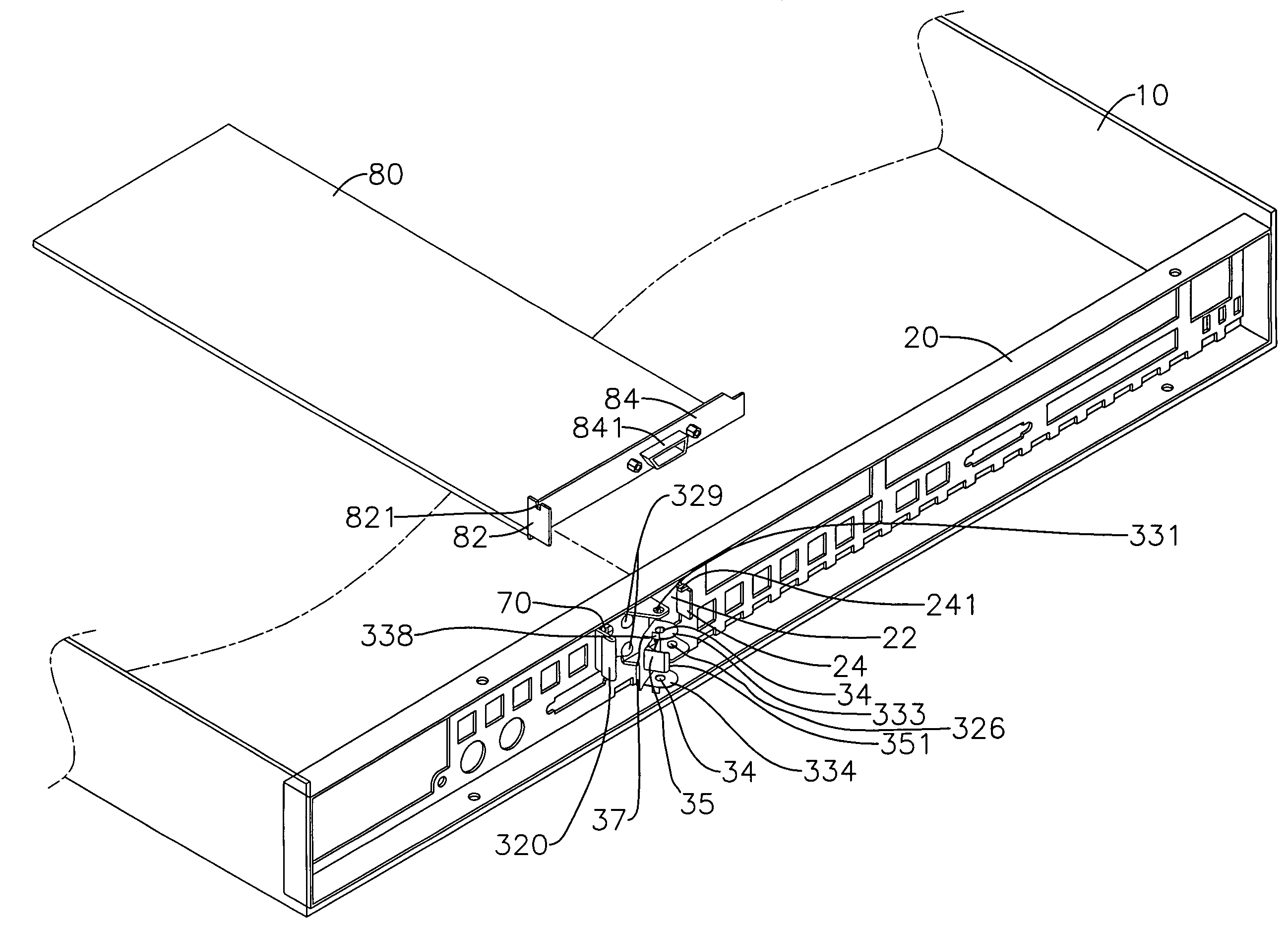
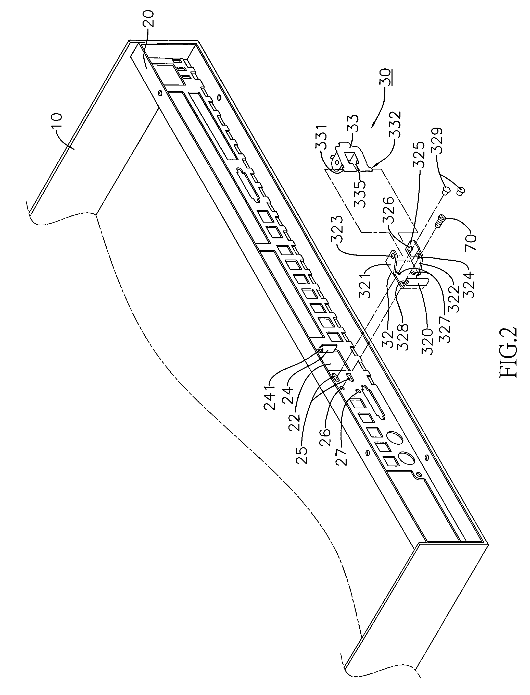
[0015]Referring to FIGS. 1 to 3, the present invention is to provide a circuit card locking device at a rear cover of a computer, including a computer casing 10, a rear side of which is connected to a rear cover 20, with a wall of the rear cover 20 being provided with a rectangular hole 22 having an outward projection piece 24 at a side edge thereof; and a locking device 30.

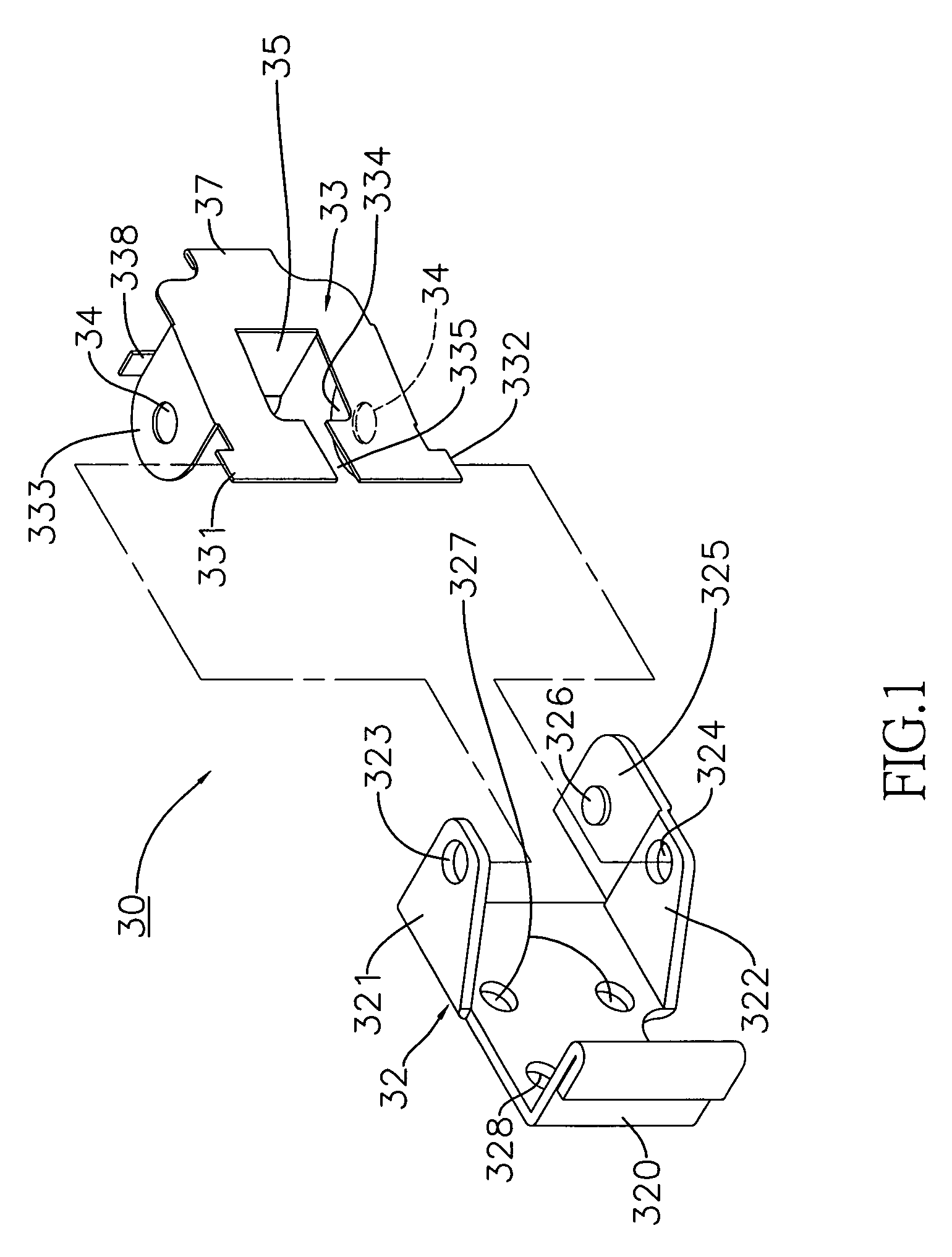
[0016]The locking device 30 is composed of a seat 32, which is fixed on a board at a side of the rectangular hole 22, and an upper and lower parts of a body of which are provided with an upper ear 321 and a lower ear 3211 respectively, with the upper and lower ears 321, 322 being provided with an upper and lower through-holes 323, 324; a locking body 33, an upper and lower parts at a rear end of which are protruded with an upper projection end 331 and a lower projection end 322 respectively, with the upper and lower projection ends 331, 332 being loosely connected into the upper and lower through-holes 323, 324 r...


PUM


Abstract

A circuit card locking device (30) at a rear cover of a computer, is composed of a computer casing (10), a rear side of which is connected with a rear cover (20) which is provided with a rectangular hole (22) and a projection piece (24) that is formed with a tab (241); a locking device (30), which tightly lock and fix a straight metallic piece (82) of a circuit card (80) at a periphery of the rectangular hole (22) of the rear cover (20). The locking device (30) has a body (3) that may be rotated from a retracted position in which it is securely held to a position in which an elastic tongue (35) of the body (3) presses on the metallic piece (82) of the circuit card (80) to urge it toward the projection piece (24) and to cause the tab (241) to lock into an indentation (821) in the metallic piece (82). Accordingly, the straight metallic piece (82) at a rear end of the circuit card (80) can be tightly locked on the rear cover (20) without using screws, and can be quickly released from the rear cover (20).

Description

BACKGROUND OF THE INVENTION[0001](a) Field of the Invention[0002]The present invention relates to a circuit card locking device at a rear cover of a computer, and more particularly to a rear cover with a locking device which can lock and fix a metallic piece at a rear side of a circuit card.[0003](b) Description of the Prior Art[0004]It is known that a conventional circuit card is always fixed on a rear cover of a computer casing with screws; therefore, when the circuit card is to be assembled on or disassembled from the rear cover, the screws should always be locked or unlocked, which is very time-consuming in operation.SUMMARY OF THE INVENTION[0005]The primary object of present invention is to provide a circuit card locking at a rear cover of a computer, such that a straight metallic piece at a rear end of the circuit card can be tightly locked on the rear cover without using screws, and can be quickly released from the rear cover.[0006]To enable a further understanding of the sai...

Claims


Application Information

Patent Timeline
Patent Type & Authority Patents(United States)
IPC IPC(8): H05K5/00
CPCG06F1/186
Inventor LIANG, CHIEN-FA
Owner SUPER MICRO COMP
Why Eureka
Try Eureka