Drive system for magnetic resistance exercisers

a technology of magnetic resistance exerciser and drive system, which is applied in the direction of belt/chain/gearing, gymnastic exercise, gearing, etc., can solve the problems of increasing the size of the flywheel, occupying too much space, and increasing the manufacturing cost accordingly

Inactive Publication Date: 2008-02-26
WU CHANG MING
View PDF4 Cites 2 Cited by
  • Summary
  • Abstract
  • Description
  • Claims
  • Application Information

AI Technical Summary

Problems solved by technology

If the ratio of speed of the fly wheel and the weight wheel is to be increased, the size of the fly wheel has to be increased and this occupies too much space and the manufacturing cost is increased accordingly.

Method used


Image

  • Drive system for magnetic resistance exercisers
  • Drive system for magnetic resistance exercisers
  • Drive system for magnetic resistance exercisers

Examples


Embodiment Construction

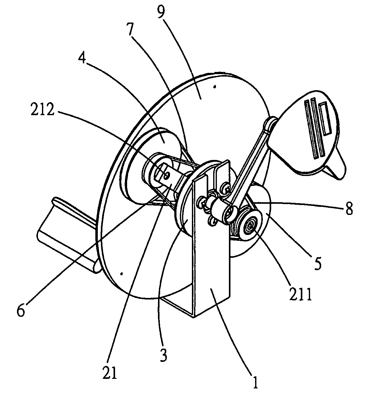
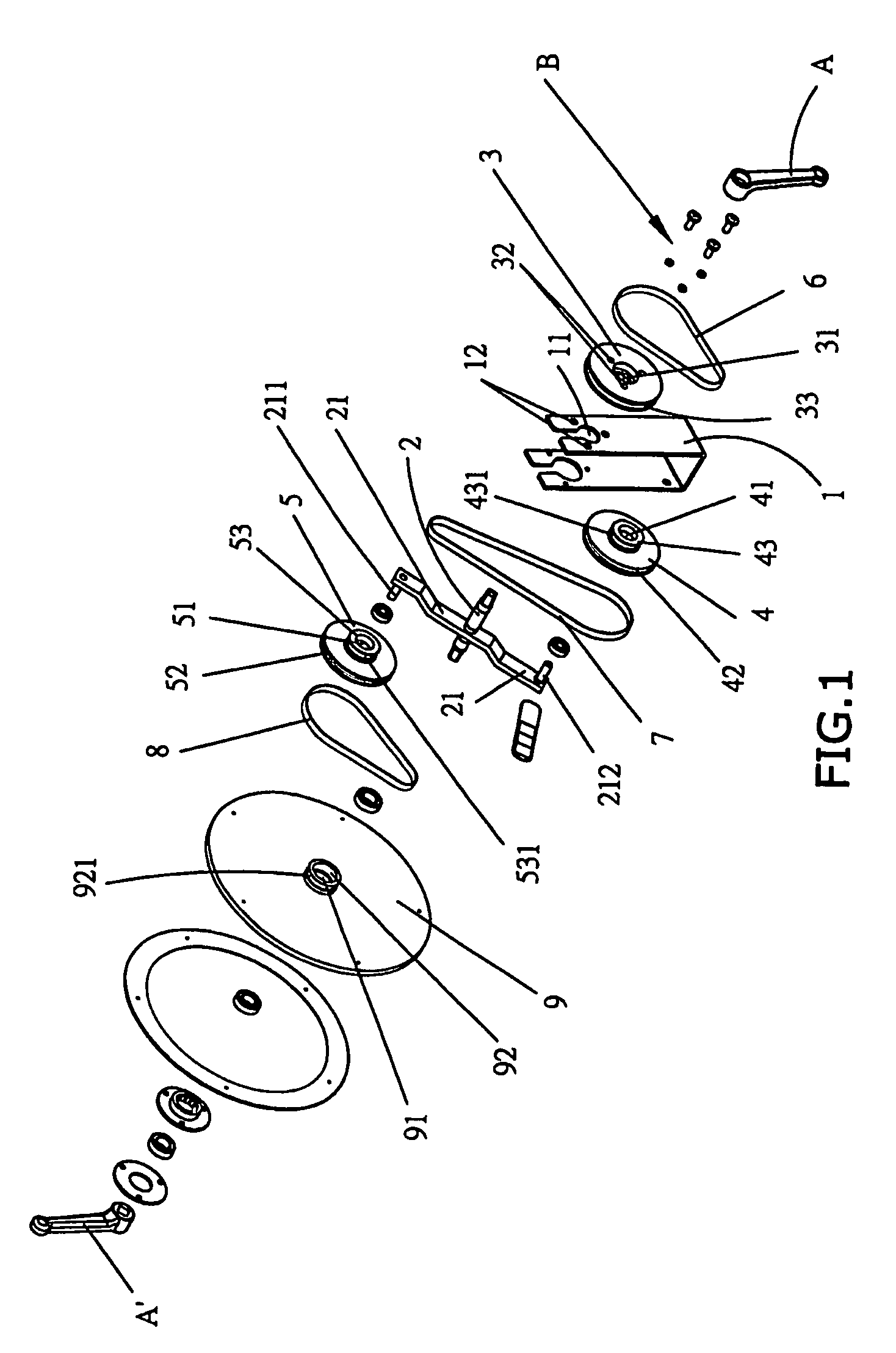
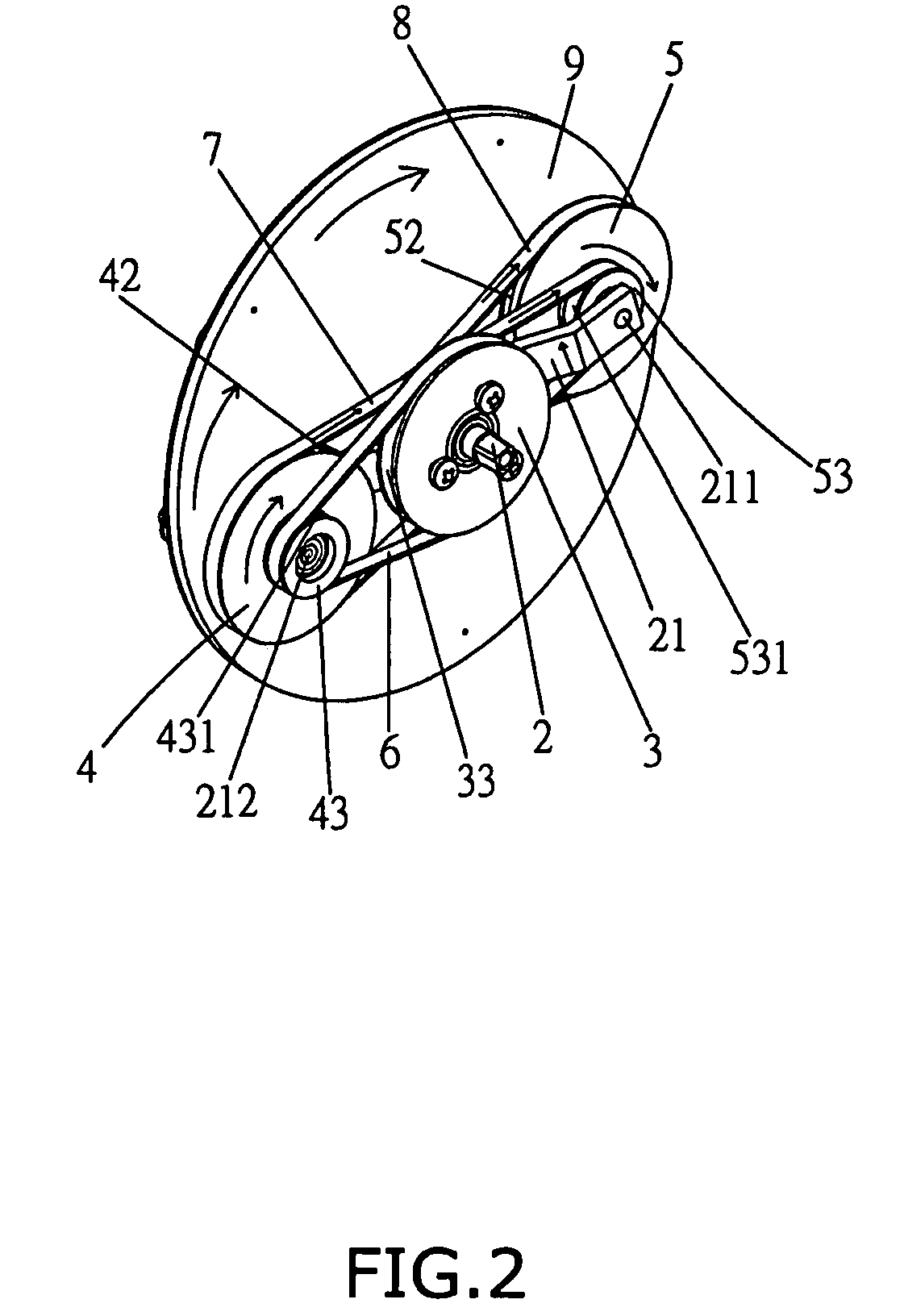
[0017]Referring to FIGS. 1 to 4, the driving system for a magnetic resistance exerciser of the present invention comprises a U-shaped support member 1 having a through hole 11 defined therethrough and a plurality of positioning holes 12 defined beside the through hole 11. A link 21 has a shaft 2 extending perpendicularly from a mediate portion thereof and two extensions 211, 212 perpendicularly extend from two ends of the link 21.

[0018]A fixed wheel 3 is fixedly connected to the support member 1 by bolts “B” extending through the positioning holes 32 in the fixed wheel 3 and fixed to the positioning holes 12 in the support member 1. A first central hole 31 is defined through the fixed wheel 3 and a belt groove 33 is defined in an outer periphery of the fixed wheel 3.

[0019]Two rotatable wheels 4, 5 each have a through hole 41 / 51 defined in a center thereof and a first groove 42 / 52 defined in an outer periphery of each of the rotatable wheels 4, 5. A first extension portion 43 / 53 exte...


PUM


Abstract

A drive system for a magnetic resistance exerciser includes a fixed wheel and at least one rotatable wheel which are rotatably connected to the weight wheel and the fixed wheel by two respective belts. The fixed wheel and the weight wheel share a common shaft which is perpendicularly connected with a link and the at least one rotatable wheel is rotatably connected to an extension on an end of the link. When rotating the shaft, the link rotates and the at least one rotatable wheel rotates about the shaft and the extension simultaneously so that the rotational speed of the weight wheel can be increased without increasing the whole system.

Description

BACKGROUND OF THE INVENTION[0001](1) Field of the Invention[0002]The present invention relates to a drive system for a magnetic resistance exerciser wherein the rotational speed of the weight wheel can be increased without increasing the whole system.[0003](2) Description of the Prior Arts[0004]A conventional magnetic resistance exerciser generally includes a fly wheel and a weight wheel which is connected to the fly wheel by a belt. The user treads the pedals to speed up the fly wheel which drives the weight wheel so as to obtain different levels of resistance. If the ratio of speed of the fly wheel and the weight wheel is to be increased, the size of the fly wheel has to be increased and this occupies too much space and the manufacturing cost is increased accordingly.[0005]The present invention intends to provide a drive system for increasing the rotational speed of the weight wheel while the fly wheel is remained the same.SUMMARY OF THE INVENTION[0006]The present invention relate...

Claims


Application Information

Patent Timeline
Patent Type & Authority Patents(United States)
IPC IPC(8): A63B22/06
CPCA63B21/154A63B21/225A63B22/0605A63B21/005
Inventor WU, CHANG MING
Owner WU CHANG MING
Why Eureka
Try Eureka