Color filter manufacturing method for a plastic substrate

a technology of plastic substrate and manufacturing method, which is applied in the direction of instruments, photomechanical devices, optical elements, etc., can solve the problems of increasing manufacturing cost and affecting the quality of color filters, and achieves the effects of less chemical corrosion, less corrosion character and increased manufacturing cos

Inactive Publication Date: 2008-02-26
IND TECH RES INST
View PDF9 Cites 6 Cited by
  • Summary
  • Abstract
  • Description
  • Claims
  • Application Information

AI Technical Summary

Benefits of technology

[0006]In order to overcome the shortages of the current color filter manufacturing method, the present invention is to provide a color filter manufacturing method for a plastic substrate. More particularly, the method is applied to the plastic substrate. The plastic substrate potentially stand less chemical corrosion than the glass substrate, and therefore, the conventional CF process of manufacturing color filters needs to be processed in many times with chemical liquids. Apart from above, it causes damages on the plastic substrate thereto influence the quality of the color filter. As a result, it needs to choose the chemical liquid of which is with less corrosion character to do CF process while using the plastic substrate to manufacture a color filter. However, the manufacturing cost is increased herein. The present invention for overcoming the problem is therefore, to provide a technique applying to the plastic substrate without processing many CF processes to implement a color filter. The method uses a re-molding technique to form a plastic substrate with multiple grooves. Then, it uses the inkjet printing method to jet three primary colors into the grooves of the above saying substrate.
[0007]Further, it processes coating on the plane layer. The feature of the process is that the substrate is one-piece to be formed thereto implement a big-area filter. Also, it does not need to use CF process thereto avoid any damages from using chemical liquids and decrease environmental pollution. Another method is that the color filtering layer jetted into the groove, and therefore, solves the coating problem caused from the surface tension by the inkjet printing method. The present invention can fully implement the purpose of manufacturing color filter based on achieving a simple manufacture and a low cost.

Problems solved by technology

Apart from above, it causes damages on the plastic substrate thereto influence the quality of the color filter.
However, the manufacturing cost is increased herein.

Method used


Image

  • Color filter manufacturing method for a plastic substrate
  • Color filter manufacturing method for a plastic substrate
  • Color filter manufacturing method for a plastic substrate

Examples


Embodiment Construction

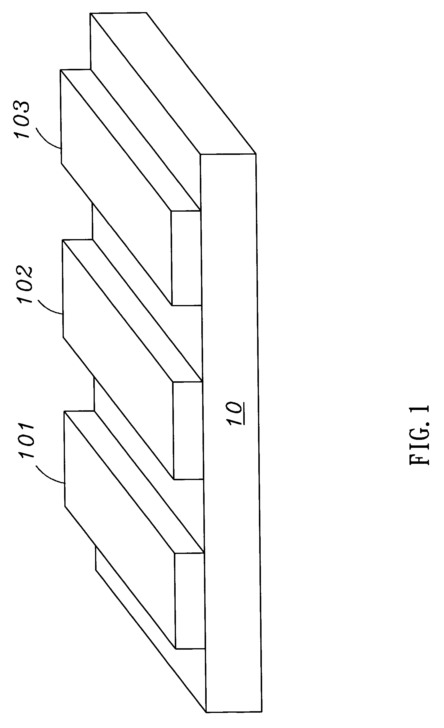
[0021]One of the color filter manufacturing methods for a plastic substrate according to the present invention uses a re-molding technique to form the plastic substrate. The master mold of the re-molding plastic substrate uses etching and electriolating techniques of LIGA LithographieGaVanoformung Abformung to implement. The LIGA technique defines the required graphs by the micro-development. Then, it processes the steps of electro-deposition, electroforming, and electriolating to perform the etching. Finally, it processes a micro molding and a micro-injection molding to form the master mold 10 in at least three-bump areas 101, 102, and 103 as shown in FIG. 1.

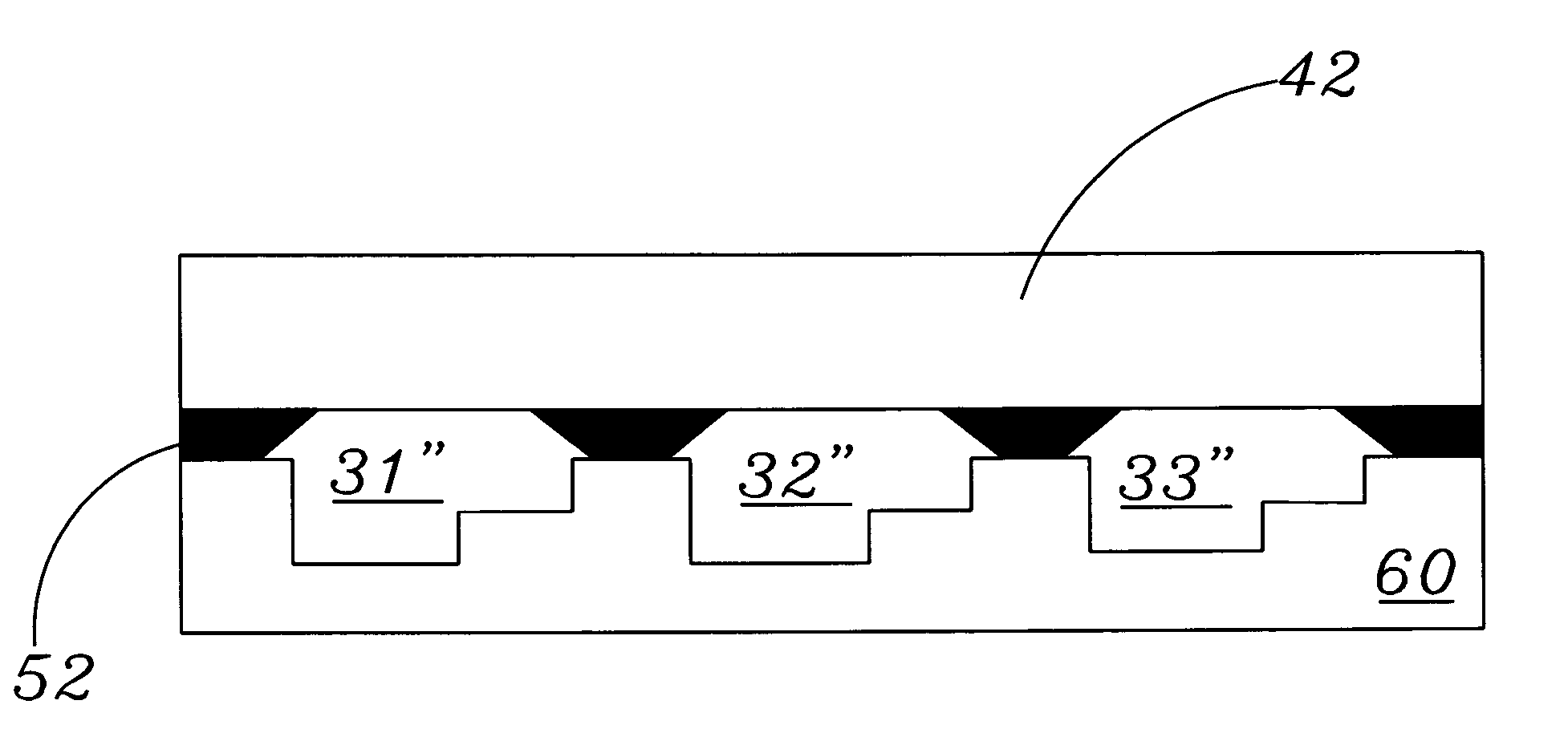
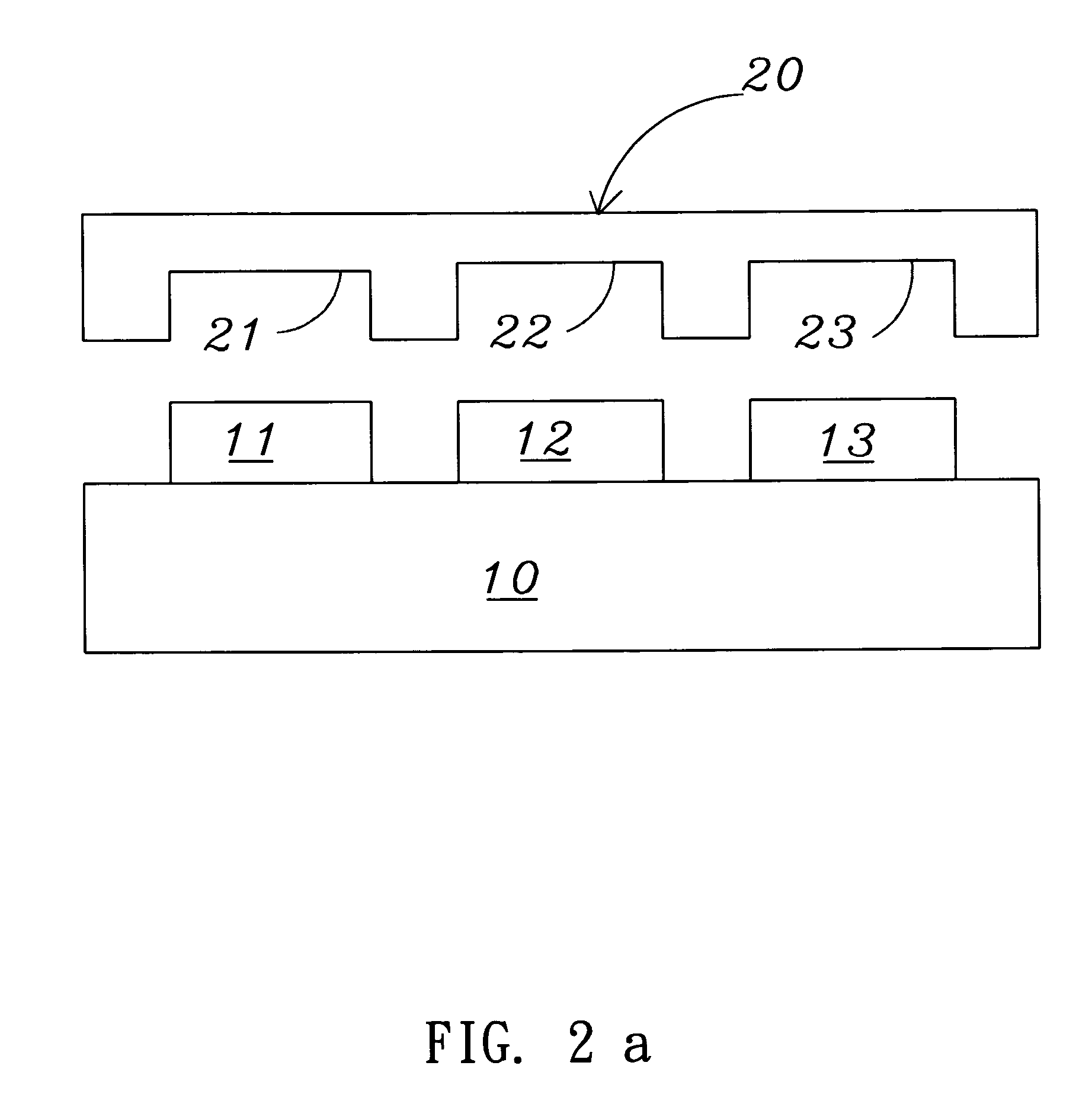
[0022]The steps of the color filter manufacturing method for a plastic substrate according to the present invention can be described below. First, please referring to FIG. 2a, it uses three-bump areas 101, 102, and 103 of the master mold 10 to extrude a substrate 20. The substrate is with three corresponding grooves 21, 22 and ...


PUM

PropertyMeasurementUnit
colorsaaaaaaaaaa
surface areaaaaaaaaaaa
weightaaaaaaaaaa

Abstract

A color filter manufacturing method for a plastic substrate uses an extrusion process to form a plastic substrate with multiple grooves. Then, it uses inkjet printing method to jet photo resists into the groove of the plastic substrate after defining the primary colors of red R., green G., and blue B. The method can overcome the problem happened in the conventional CF photolithography process. This, therefore, can simplify the manufacturing process, and can apply to the large-area plastic substrate of a color filter.

Description

BACKGROUND OF THE INVENTION[0001]1. Field of the Invention[0002]The present invention relates to a color filter manufacturing method for a plastic substrate. More particularly, it uses an inkjet printing method to jet photo resists into the groove of the plastic substrate.[0003]2. Description of the Prior Art[0004]Liquid crystal displays have the advantages of small volume, light weight, low power consumption, low radiation, excellent image quality, broad applications, and are widely applied in the consumer electronic products or computer products, such as medium to small portable TVs, mobile phones, camcorders, notebook computers, desktop computers and projection TVs, etc. More particularly, the main stream of LCD is using in flat panel display system. The key component for presenting better brightness, vividness, and color-ness in liquid crystal displays is in the color filter. Therefore, the color filter has a full potential in the LCD development. The biggest market of the color...

Claims


Application Information

Patent Timeline
Patent Type & Authority Patents(United States)
IPC IPC(8): B29C59/00B29C70/30B41J2/01G02B5/20G02F1/1335G03F7/00
CPCG02B5/201G03F7/0007
Inventor HUANG, LIANG-YINGCHAN, CHING-HSIANGHO, JIA-CHONGLIAO, CHI-CHANGHSIN, LUNG-PIN
Owner IND TECH RES INST
Why Eureka
Try Eureka