Method for aligning radiographic inspection system

a radiographic inspection and detector technology, applied in the field of radiographic inspection systems, can solve problems such as unnecessary exposure to x-rays

Inactive Publication Date: 2008-03-11
GENERAL ELECTRIC CO
View PDF16 Cites 18 Cited by
  • Summary
  • Abstract
  • Description
  • Claims
  • Application Information

AI Technical Summary

Problems solved by technology

Because X-Rays are ionizing radiation and dangerous to humans, means are required to prevent or minimize personnel exposure.
Depending on the size and configuration of the object and system, the detector and X-Ray tube may not be within line of sight of each other, or even be seen from a single separate location, making alignment of the source, detector, and shielding difficult
For inspection of large objects, this is often difficult, slow, and can result in unnecessary exposure to X-Rays.

Method used


Image

  • Method for aligning radiographic inspection system
  • Method for aligning radiographic inspection system
  • Method for aligning radiographic inspection system

Examples


Embodiment Construction

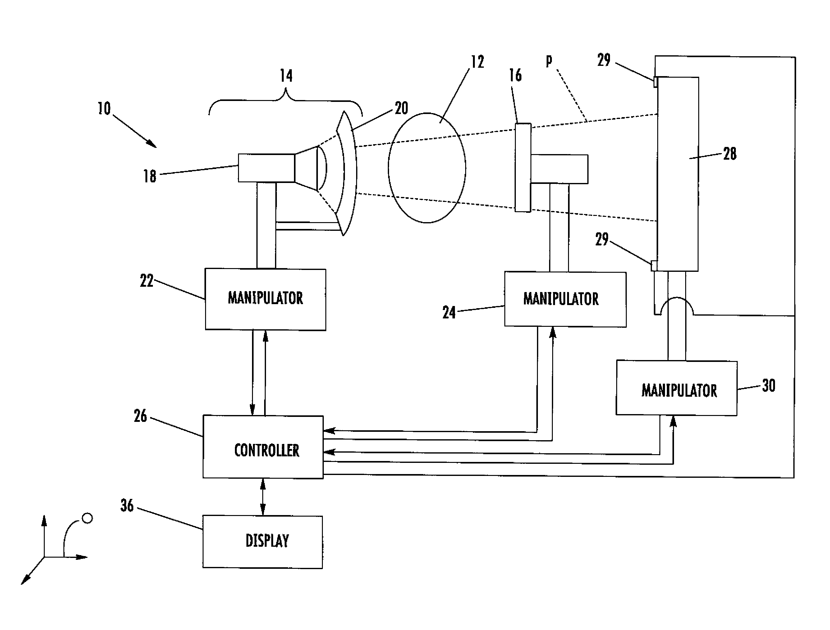
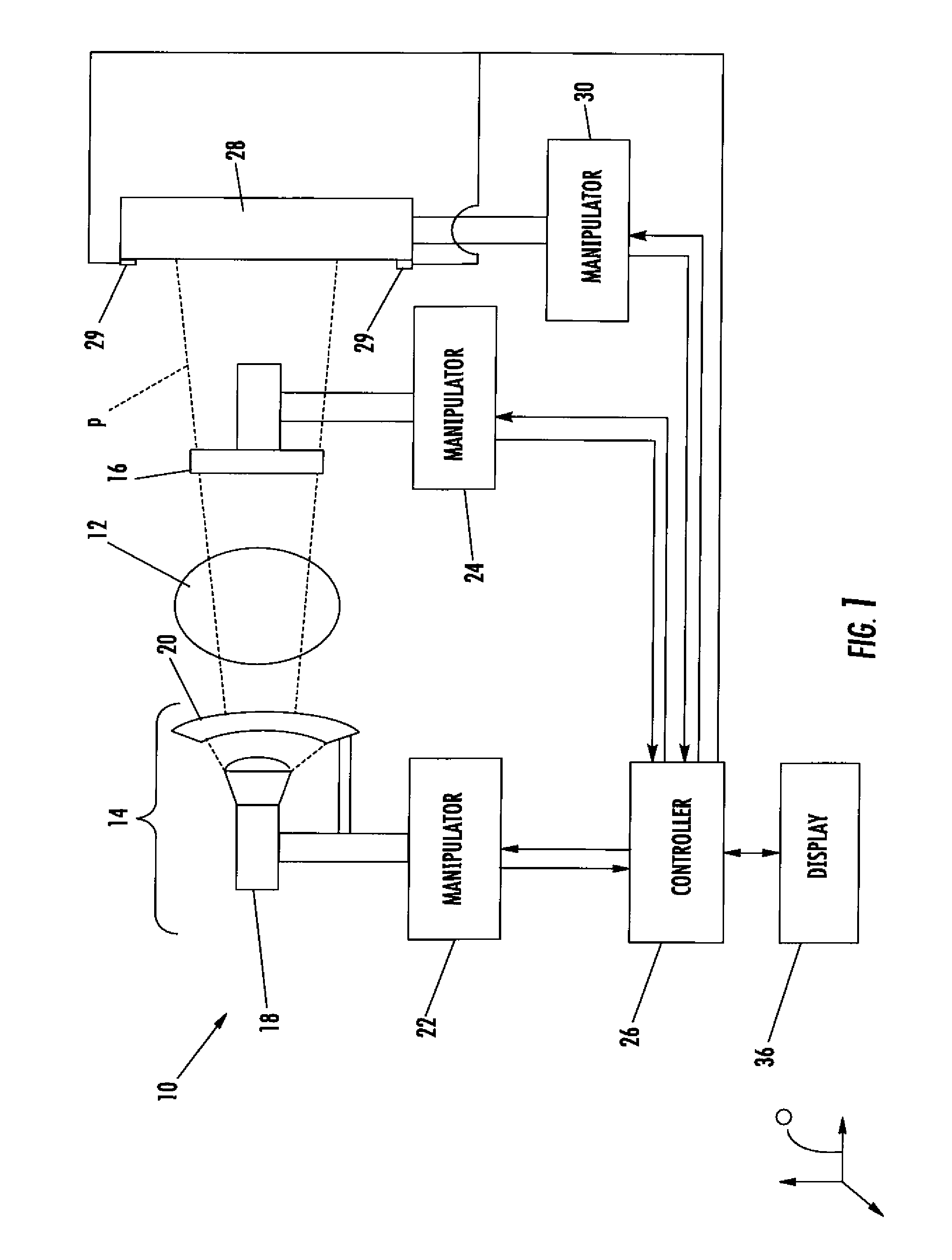
[0013]Referring to the drawings wherein identical reference numerals denote the same elements throughout the various views, FIG. 1 illustrates schematically a radiographic inspection system 10 disposed around a target 12 to be inspected. The inspection system 10 may be used with various types of structures. The inspection system 10 includes a radiation source 14 located on a first side of the target12 and a radiation detector 16 located on a second, opposite side of the target 12. The radiation source 14 includes an X-ray tube 18 (an isotopic source could also be used), and may include a collimator 20 of a known type which defines radiation flux generated by the tube 18 into beam. In the illustrated example, the beam (described in more detail below) is cone or fan shaped, but the beam may also be collimated to the shape and size of the detector, or in come cases even collimated in any number of ways to illuminate a particular airframe section and to block out anything around the poi...


PUM


Abstract

A method for aligning a radiographic inspection system includes providing a radiation source capable of emitting a beam pattern, positioning a detector to receive radiation emitted from the radiation source, and causing the radiation source to emit the beam pattern. The detector is used to determine the distribution of flux intensity of the beam pattern. A two-dimensional or three-dimensional map of the beam pattern may be stored. The system is aligned by positioning the radiation source and the detector with reference to the map, so that the detector is disposed at a predetermined location within the beam pattern.

Description

BACKGROUND OF THE INVENTION[0001]This invention relates generally to radiographic inspection system, and more particularly to a method of aligning a radiographic source with a detector.[0002]Radiographic apparatus, particularly X-ray apparatus, is used to measure or inspect an object for the purposes of evaluating its characteristics. Radiation projected by a source is absorbed to varying degrees by the inspected object, depending on its size, mass, and configuration. The photons that continue through the object are counted or measured by a detector, and the pattern of flux variation across the object provides information about it. To obtain an optimum image, the X-Ray source, detector, and inspected object must be aligned. Small improvements in this alignment can often provide significant improvement in image quality.[0003]Because X-Rays are ionizing radiation and dangerous to humans, means are required to prevent or minimize personnel exposure. This is accomplished by designating ...

Claims


Application Information

Patent Timeline
Patent Type & Authority Patents(United States)
IPC IPC(8): A61B6/08
CPCG01N23/04
Inventor BIRDWELL, THOMAS WILLIAM
Owner GENERAL ELECTRIC CO
Why Eureka
Try Eureka