Inspection tool for radiographic systems

a radiographic inspection and tool technology, applied in the direction of x-ray equipment, electrical equipment, etc., can solve the problems of time-consuming, cumbersome task, loss of productivity,

Inactive Publication Date: 2009-04-02
GENERAL ELECTRIC CO
View PDF10 Cites 6 Cited by
  • Summary
  • Abstract
  • Description
  • Claims
  • Application Information

AI Technical Summary

Problems solved by technology

In most situations, determining the right x-ray technique for an inspection process using trial experiments is time consuming.
Using a trial method to calculate the exposure parameters for each type of source and for a specific object could be a cumbersome task.
Since the exposure parameters may be different for the different objects, the increased time for accurately determining the exposure parameters leads to loss in productivity.

Method used


Image

  • Inspection tool for radiographic systems
  • Inspection tool for radiographic systems
  • Inspection tool for radiographic systems

Examples


Embodiment Construction

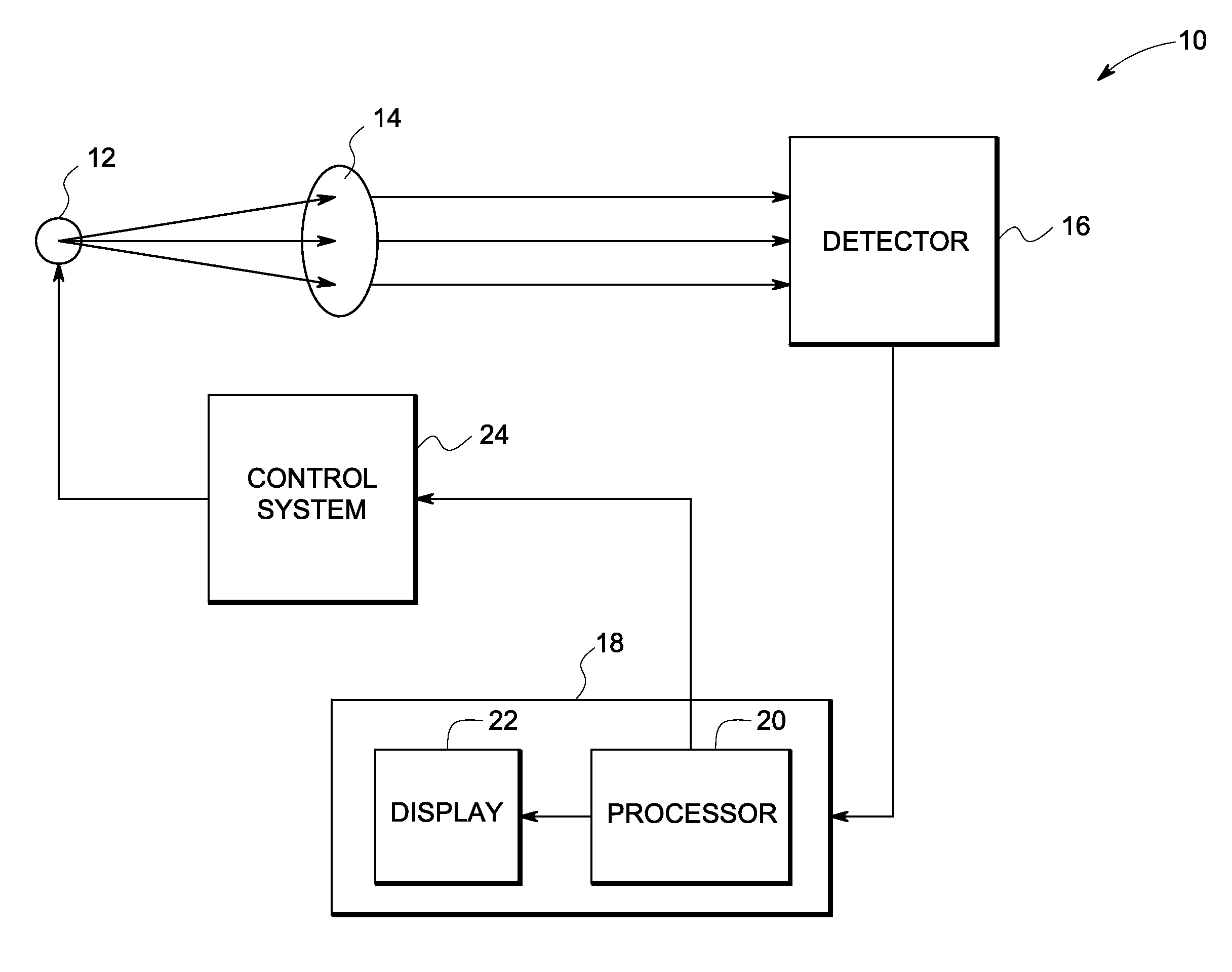
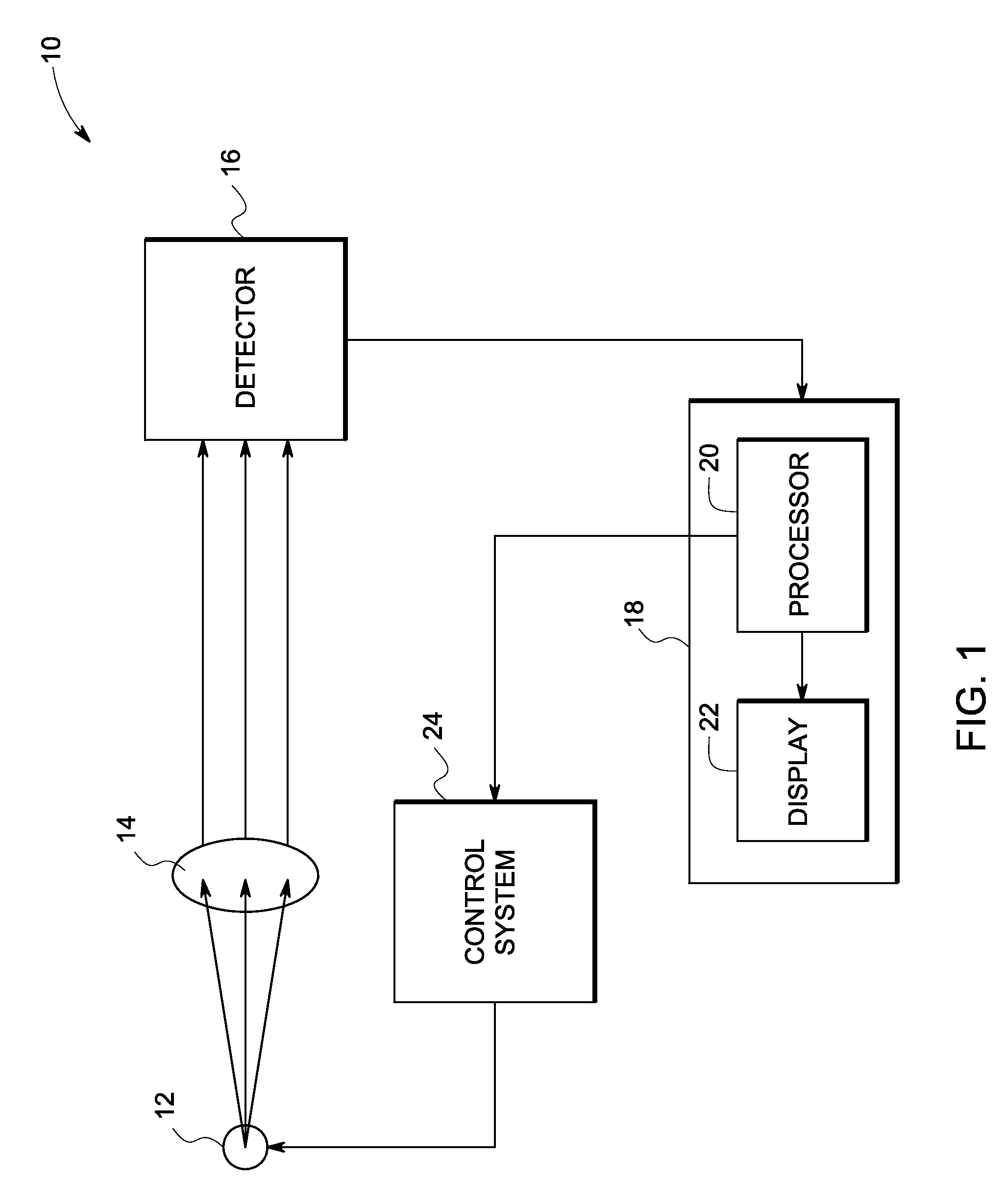
[0013]FIG. 1 is a block diagram of one embodiment of a radiographic inspection system implemented in accordance with one aspect of the invention. Radiographic inspection system 10 comprises a radiation source 12, object 14, a detector 16, a processor 18 and a control system 24. Each component is described in further detail below.

[0014]As used herein, “adapted to”, “configured” and the like refer to mechanical or structural connections between elements to allow the elements to cooperate to provide a described effect; these terms also refer to operation capabilities of electrical elements such as analog or digital computers or application specific devices (such as an application specific integrated circuit (ASIC)) that are programmed to perform a sequel to provide an output in response to given input signals.

[0015]Radiation source 12 is configured to generate x-ray spectrum for given voltage, current, target and filters to irradiate an object 14. In one embodiment, the radiation sourc...


PUM


Abstract

A system for radiographic inspection of an object is provided. The system comprises a radiation source configured to generate radiation, a display unit for generating a graphical user interface (GUI) including multiple fields. A user provides input data via the fields in the GUI. A processor configured to compute a plurality of exposure parameters based on the input data and a control system is configured to initialize the radiation source with the exposure parameters.

Description

BACKGROUND[0001]The invention relates generally to industrial radiography and more specifically to an inspection-planning system for radiographic inspection[0002]Conventionally, in radiographic inspection systems, a beam of high-energy radiation such as X-rays or Gamma rays is transmitted through a test object to be inspected and a corresponding image of the test object is formed on the imaging devices. A flaw, defect or structural inhomogeneity in the test object is detected by examining the image generated.[0003]For reliable inspection, the image should have desired image quality. The image quality is governed by various parameters such as contrast, signal to noise ratio and spatial resolution. To obtain the desired image quality, suitable radiographic exposure parameters need to be selected. In existing radiographic inspection systems, the desired exposure parameters are obtained after performing several trial experiments.[0004]In most situations, determining the right x-ray tech...

Claims


Application Information

Patent Timeline
Patent Type & Authority Applications(United States)
IPC IPC(8): H05G1/46
CPCH05G1/30
Inventor VENUGOPAL, MANOHARANGOPALIKA, NITYANANDMEETHAL, MANOJ KUMARMISHRA, DEBASISH
Owner GENERAL ELECTRIC CO
Why Eureka
Try Eureka