
Safety switch, and enclosure and electrical connector assembly therefor

a safety switch and enclosure technology, applied in the field of enclosures for safety switches, can solve the problems of limiting the available options for providing secondary power, presenting a serious safety concern,

Active Publication Date: 2008-03-25
EATON INTELLIGENT POWER LIMITED
View PDF6 Cites 23 Cited by
  • Summary
  • Abstract
  • Description
  • Claims
  • Application Information

AI Technical Summary

Benefits of technology

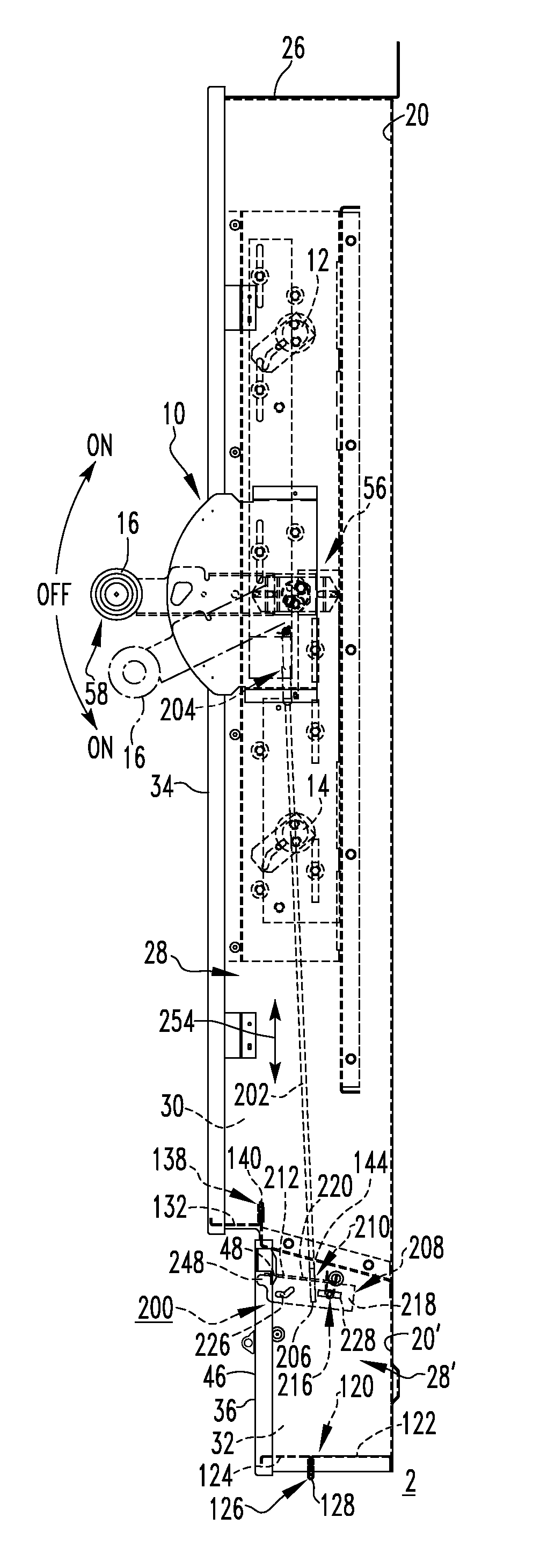
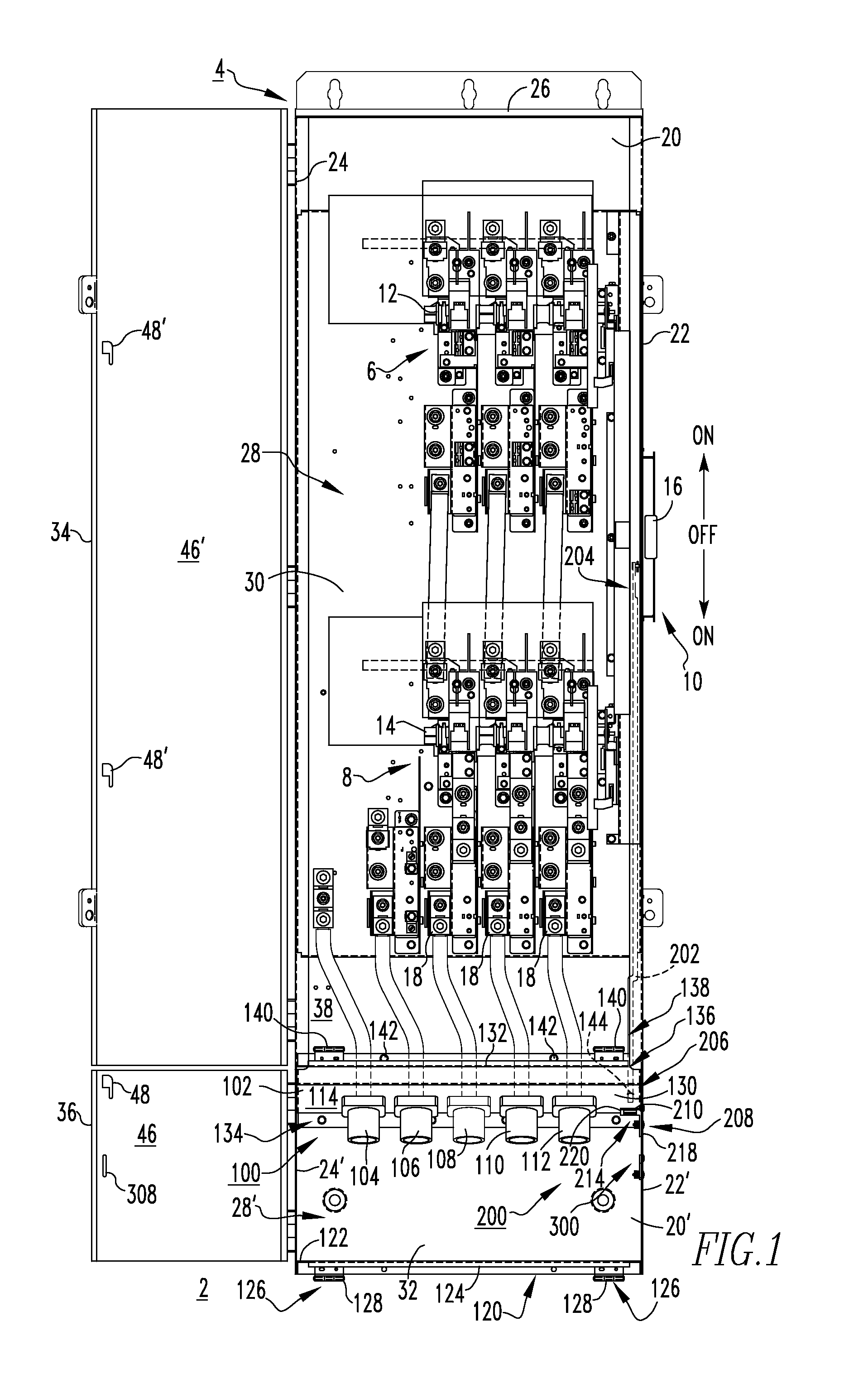
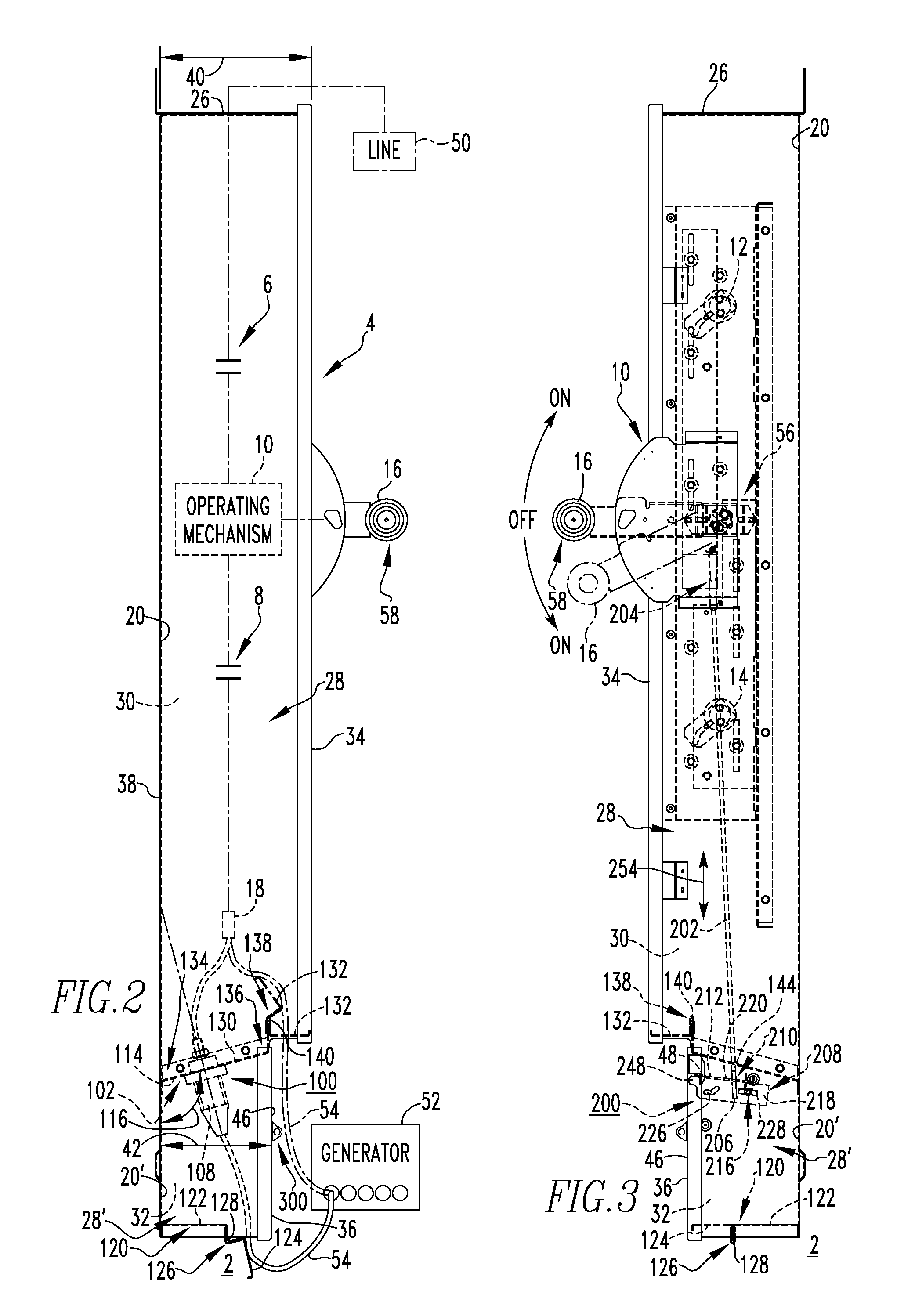
[0019]The electrical switching apparatus may be a safety switch. The back panel of the first compartment of the enclosure and the back panel of the second compartment of the enclosure may comprise different sections of the same piece of material. The first cover may be a first door pivotably coupled to a corresponding one of the sidewalls of the first compartment, and the second cover may be a second door pivotably coupled to a corresponding one of the sidewalls of the second compartment.

Problems solved by technology

This presents a serious safety concern.
This undesirably limits the available options with respect to providing secondary power.

Method used


Image

  • Safety switch, and enclosure and electrical connector assembly therefor
  • Safety switch, and enclosure and electrical connector assembly therefor
  • Safety switch, and enclosure and electrical connector assembly therefor

Examples


Embodiment Construction

[0027]Directional phrases used herein, such as, for example, left, right, top, bottom, upper, lower, front, back, clockwise, counterclockwise and derivatives thereof, relate to the orientation of the elements shown in the drawings and are not limiting to the claims unless expressly recited therein.

[0028]As employed herein, the terms “fastener” and “fastening mechanism” refer to any suitable connecting or tightening material or device expressly including, but not limited to, rivets (e.g., without limitation, pop rivets), screws, bolts and the combinations of bolts and nuts (e.g., without limitation, lock nuts) and bolts, washers (e.g., without limitation, lock washers) and nuts.

[0029]As employed herein, the term “linkage” refers to any known or suitable mechanism for interconnecting one component to another component in order to provide mechanical communication therebetween and expressly includes, without limitation, a rigid member, such as a tube, a rod, a shaft, a movable (e.g., wi...


PUM


Abstract

An electrical connector assembly is provided for an electrical switching apparatus including an enclosure, separable contacts housed by the enclosure, and an operating mechanism structured to open and close the separable contacts. The enclosure has a back panel, sidewalls extending outwardly from the back panel, an exterior and an interior having a plurality of compartments. A first compartment houses the separable contacts and includes a first cover. A second compartment is disposed adjacent the first compartment and includes a second cover. The electrical connector assembly includes a plate member disposed between the first and second compartments, and a plurality of electrical connectors coupled to the plate member and being substantially disposed within the second compartment. The electrical connectors are structured to be electrically connected to the separable contacts, and are substantially inaccessible when the second compartment is covered by the second cover.

Description

CROSS-REFERENCE TO RELATED APPLICATION[0001]This application is related to commonly assigned, concurrently filed:[0002]U.S. patent application Ser. No. 11 / 673,772, filed Feb. 12, 2007, entitled “Electrical Switching Apparatus and Interlock Assembly Therefor”.BACKGROUND OF THE INVENTION[0003]1. Field of the Invention[0004]The invention relates generally to electrical switching apparatus and, more particularly, to enclosures for safety switches. The invention also relates to electrical connector assemblies for safety switches.[0005]2. Background Information[0006]Safety switches are used in electrical power distribution systems in order to electrically isolate a load or a portion of a power circuit.[0007]Typically, safety switches include an operating mechanism housed within an enclosure, such as a sheet metal cabinet. The operating mechanism includes an operating handle, which typically has either a single-throw configuration, in which the operating handle is operable between two posi...

Claims


Application Information

Patent Timeline
Patent Type & Authority Patents(United States)
IPC IPC(8): H02B13/02
CPCH01H9/22H01H2300/018H01R13/6397H02B1/305
Inventor FOLEY, BRENDAN A.CARSON, EDDIE D.BENDER, DOUGLAS R.WILKIE, WILLIAM E.PROHASKA, RICHARD D.
Owner EATON INTELLIGENT POWER LIMITED
Learn More