Fluid ejection device nozzle array configuration

a technology of nozzle array and ejection device, which is applied in the direction of printing and inking apparatus, etc., can solve the problems of prohibitively expensive, too large die size, and inability to make high-quality printing arrays which are comprised of a single di

Inactive Publication Date: 2008-04-01
EASTMAN KODAK CO
View PDF11 Cites 214 Cited by
  • Summary
  • Abstract
  • Description
  • Claims
  • Application Information

AI Technical Summary

Problems solved by technology

However, in some applications, forming all of the required arrays on one die may cause the die size to grow so large that it is too costly.
Due to fabrication yield, it may be prohibitively expensive to make high quality printing arrays which are comprised of a single die, which would need to be at least 20 cm long.
A disadvantage of multiple groups of nozzles arranged on an edgeshooter is that the nozzle resolution is limited by the requirement that all of the nozzles be arranged in a single line.
In addition, it is sometimes useful to provide different sized drop ejectors corresponding to the different liquids that are being ejected.
One drawback of this configuration where the two different arrays of black drop ejectors are on separate printheads is that it is difficult to align the separate printheads such that the spots from different black arrays are precisely positioned with respect to one another with an alignment error of less than one pixel spacing.

Method used


Image

  • Fluid ejection device nozzle array configuration
  • Fluid ejection device nozzle array configuration
  • Fluid ejection device nozzle array configuration

Examples


first embodiment

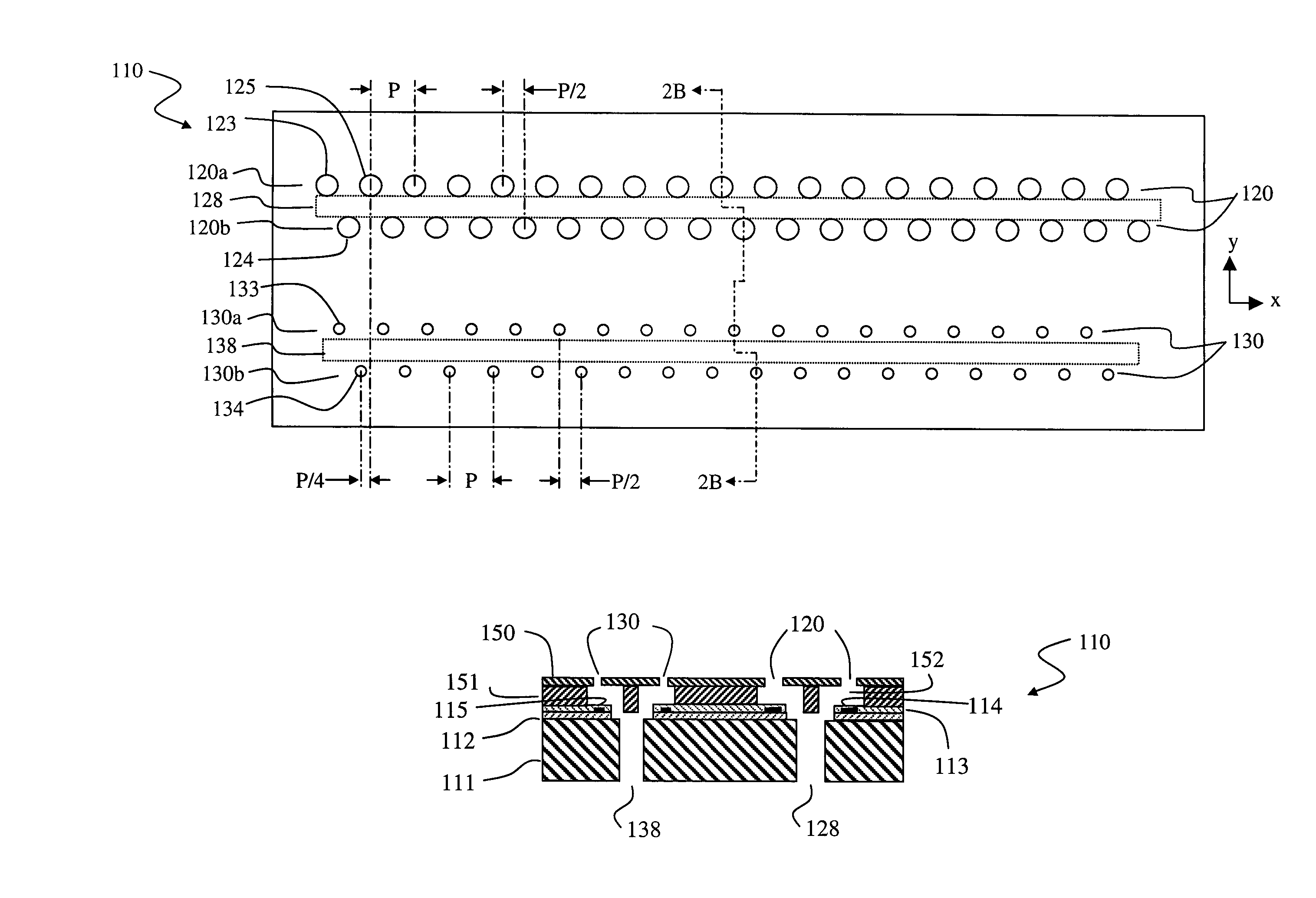
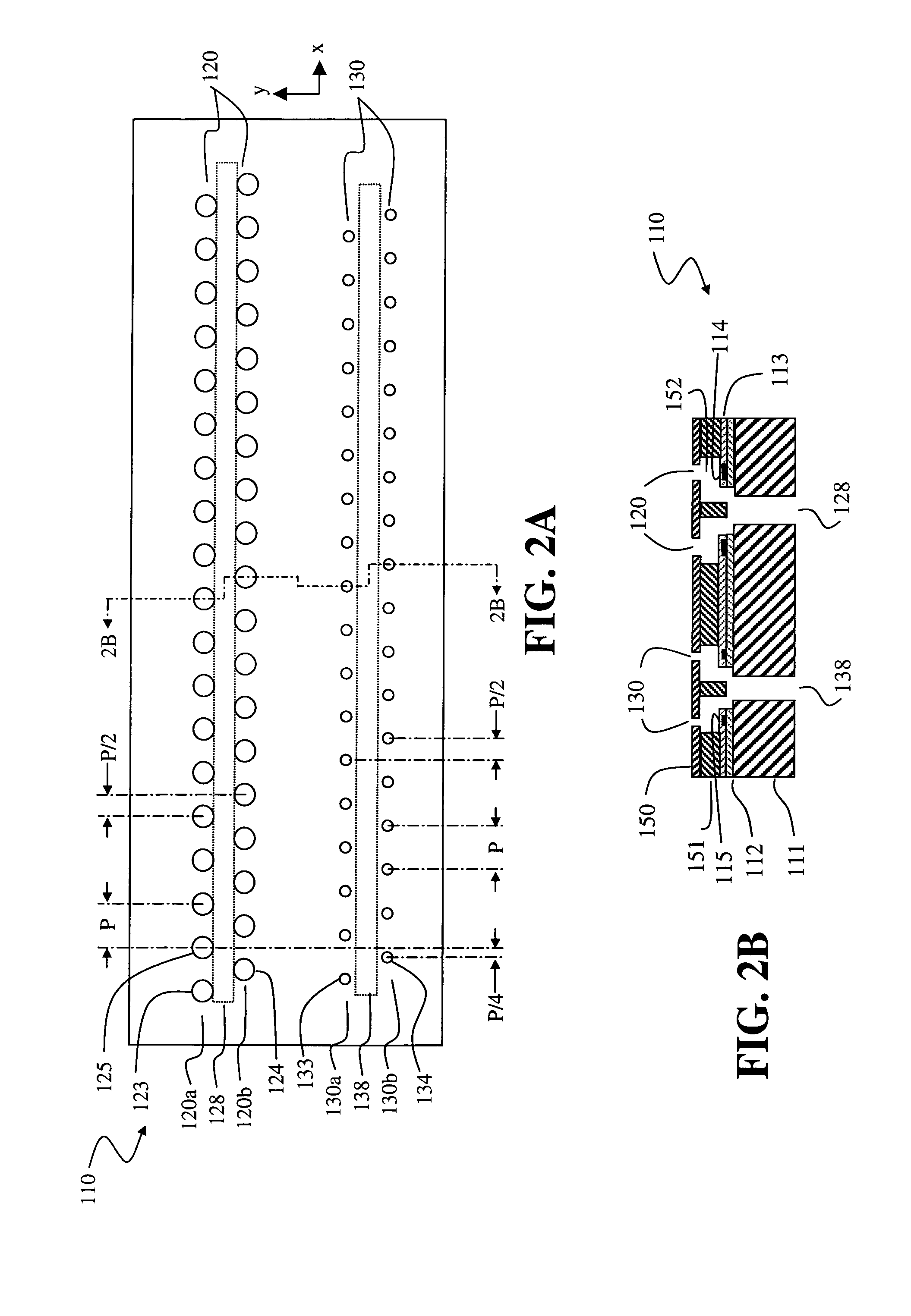
[0036]FIG. 2 shows a fluid ejection device 110 of this invention. Fluid delivery slots 128 and 138 are formed through substrate 111. The fluid delivery slots extend along the length of the substrate in the x direction, each slot thereby forming a channel to supply fluid to the nozzles arranged along its respective length. Nozzle array 120 is composed of two groups of nozzles. Nozzle group 120a is arranged along one side of fluid delivery slot 128 and nozzle group 120b is arranged along the other side of slot 128. Nozzle groups 130a and 130b are similarly arranged with respect to fluid delivery slot 138. Nozzle array 120 is spaced apart from nozzle array 130 in the y direction. Nozzles in each subgroup are shown as being arranged in a straight line in the x direction. In some applications, adjacent nozzles within each subgroup may be designed with a slight offset in the y direction, for example arranged in a sawtooth pattern. Generally speaking, the nozzles are arranged along the flu...

second embodiment

[0041]FIG. 3 shows a fluid ejection device 116 of this invention. In this embodiment the fluid pathway for nozzle array 120 goes around a long edge of the substrate, leading to channel 129 which extends along the x direction and supplies fluid to the array. Nozzles in array 120 are spaced at pitch P along one side of channel 129. The nozzles in array 130 are arranged similarly with respect to fluid channel 139 which is on the opposite long edge of the substrate. Nozzles in array 130 are spaced at pitch P and are also offset in the x direction from corresponding nozzles in array 120 by a distance P / 2. Thus, from left to right, the nozzles in the fluid ejection device alternate between nozzles of larger opening area from array 120 and nozzles of smaller opening area from array 130. The distance along x between two successive nozzles on fluid ejection device 110 is P / 2.

third embodiment

[0042]FIG. 4 shows a fluid ejection device 117 of this invention. In this embodiment, nozzles in the first array 120 are supplied with fluid around the edge of the substrate, as in FIG. 3, while nozzles in the second array 130 are supplied with fluid from a slot in the substrate, as in FIG. 2. Nozzles in array 120 are spaced at pitch P along one side of channel 129. Nozzle array 130 is composed of two groups of nozzles. Nozzle group 130a is arranged along one side of fluid delivery slot 138 and nozzle group 130b is arranged along the other side of slot 138. Both nozzle groups 130a and 130b are arranged at pitch P, with nozzles in group 130a offset along the x direction from nozzles in group 130b by a distance P / 2. In the configuration shown in FIG. 4, there is zero offset in the x direction between nozzles in array 120 and nozzles in group 130a, while there is an offset of P / 2 between nozzles in array 120 and nozzles in group 130b. Alternatively (not shown), there could be a nonzero...


PUM


Abstract

A fluid ejection device and a printhead including one or more such fluid ejection devices are provided. The fluid ejection device includes a substrate having a first nozzle array and a second nozzle array, each array having a plurality of nozzles and being arranged along a first direction, the first nozzle array being arranged spaced apart in a second direction from the second nozzle array. A first fluid delivery pathway is in fluid communication with the first nozzle array, and a second fluid delivery pathway is in fluid communication with the second nozzle array. Nozzles of the first nozzle array have a first opening area and are arranged along the first nozzle array at a pitch P. Nozzles of the second nozzle array have a second opening area, the second opening area being less than the first opening area. At least one nozzle of the second array is arranged offset in the first direction from at least one nozzle of the first array by a distance which is less than pitch P. A printhead comprises one or more such fluid ejection devices arranged on a support member.

Description

FIELD OF THE INVENTION[0001]The present invention relates, generally, to fluid ejection systems and, more particularly, to fluid ejection devices associated with these systems.BACKGROUND OF THE INVENTION[0002]Ink jet printing systems are one example of digitally controlled fluid ejection devices. Ink jet printing systems are typically categorized as either drop-on-demand printing systems or continuous printing systems.[0003]Drop-on-demand printing systems incorporating a heater in some aspect of the drop forming mechanism are known. Often referred to as “bubble jet drop ejectors” or “thermal ink jet drop ejectors”, these mechanisms include a resistive heating element(s) that, when actuated (for example, by applying an electric current to the resistive heating element(s)), vaporize a portion of a fluid contained in a fluid chamber creating a vapor bubble. As the vapor bubble expands, liquid in the liquid chamber is expelled through a nozzle orifice. When the mechanism is de-actuated ...

Claims


Application Information

Patent Timeline
Patent Type & Authority Patents(United States)
IPC IPC(8): B41J2/21
CPCB41J2/1404B41J2/155B41J2/2125B41J2202/20B41J2002/14475
Inventor DIETL, STEVEN J.BILLOW, STEVEN A.BLAND, WILLIAM E.CHWALEK, JAMES M.
Owner EASTMAN KODAK CO
Why Eureka
Try Eureka