Temperature measuring device and temperature measuring method

a technology of temperature measurement and measuring device, which is applied in the direction of thermometer testing/calibration, instruments, heat measurement, etc., can solve the problems of difficult to stably hold the rod-like shaped temperature detecting part, and difficult to precisely detect a body temperature, so as to eliminate the inaccuracy-causing factors in the measurement of temperature and achieve stable and precise temperature measurement.

Inactive Publication Date: 2008-04-08
SAKANO KAZUHITO +2
View PDF19 Cites 41 Cited by
  • Summary
  • Abstract
  • Description
  • Claims
  • Application Information

AI Technical Summary

Benefits of technology

[0036]When the on-subject surface temperature measuring device is actually in electromagnetic communication with the external device, electric energy is electromagnetically supplied thereto. Accordingly, the on-subject surface temperature measuring device is able to have a batteryless structure and can be formed into a compact, lightweight and thin sheet- or label-like structure. Further, the on-subject surface temperature measuring device is free from battery replacement and thus can be used semipermanently as a thermometer. Since the on-subject surface temperature measuring device simply comprises a printed antenna coil and one chip or several chips as electronic parts, production cost can greatly be reduced. This enables the on-subject surface temperature measuring device to be used as a disposable one.
[0038]The above-described indirect mode of temperature detection with the interposition of the air layer is effective for solving the problems inherent in the conventional temperature measuring devices, particularly clinical thermometers. This is because it is possible by the indirect mode to eliminate inaccuracy-causing factors in measurement of temperatures, which would cause variations in results if temperature data detecting means were directly applied to body surfaces by the medium of the adhesive material, due to irregularities dependent upon products in application thicknesses of the adhesive material, or changes in quantities of heat conducted from subject body surfaces attributable to changes in adhesion or the like in the course of uses after applications to the body surfaces, thereby enabling stable and precise temperature measurement.

Problems solved by technology

However, if such a rod-like shaped temperature detecting part is put under an armpit, there are difficulties as follows.
In the case of a thin figured parson, it is difficult to stably hold the rod-like shaped temperature detecting part because a gap is likely to be formed under the person's armpit from the first.
Particularly in a case of an old person, it is difficult to precisely detect a body temperature because the person's muscle has become weak and flabby and an enlarged gap is consequently tends to be formed under the person's armpit.
In the case of a suckling or an infant, it is not easy to stably and continuously hold the rod-like shaped temperature detecting part over a temperature detecting period of a several minutes, and it is accordingly difficult to precisely detect a body temperature.
It is, however, too stringent to impose such a restrained condition on a suckling or an infant.
Accordingly, it is difficult to precisely measure a body temperature.
In the case of rectal thermometry, hygienic management such as sterilization of a thermometer is cumbersome.
Accordingly, rectal thermometry is not suitable for body temperature measurement in a general household.
Accordingly, it is difficult to effect precise calculation for the estimation.
Accordingly, such an electronic thermometer is not suitable for monitoring a succession of subject body temperatures in real time.
This imposes the trouble of reading and recording a temperature indication every time a measured temperature is indicated on a user (a nurse mainly in a clinic or hospital).
In Japanese Unexamined Patent Publication No. 133030 / 1988, however, a wire communication mode is employed in which the thermometer attached to a body surface and the external device are connected by a cable, leading to poor manageability.
Moreover, there is a problem that when a battery is replaced, a stress is likely to be exerted on soldered part in the circuit element because of the flexibility of the substrate to cause a failure.
This poses a problem in repeated use.
However, when the external cable is connected to the fixed connector provided on the flexible substrate attached to a body surface, a strong stress is likely to be exerted on the circuit element mounted on the flexible substrate to cause a failure.
Further, it is easily supposable that if the external cable is connected to and disconnected from the connector as often as a temperature is measured, it is easily supposable that possibility of a failure increases.
On the other hand, in a case where the cable is left connected, if the cable is pulled, an excessive stress can be exerted depending upon the condition of the pulling on the connector of the electronic thermometer and a connector of the cable to cause a failure of the fitting therebetween.
Accordingly, it is pointed out that this constitutes a major factor of a contact failure or the like.
A subject with the electronic thermometer of Japanese Unexamined Patent Publication No. 133030 / 1988 attached on a body surface thereof has such an inconvenience that the subject's own freedom of movement is restricted when the electronic thermometer is connected to an external appliance by a cable.
Further, the external appliance and the electronic thermometer are put in a one-to-one relationship to thereby lead to poor working efficiency of the external appliance.
On the other hand, if a plurality of input ports are provided with an external appliance and a plurality of electronic thermometers are connected thereto in parallel, cost of the external appliance per se is increased, and besides this, each of subjects has an inconvenience of being put under a further restrained condition in order to prevent a plurality of cables from being entangled.
The structure as a whole has many parts, and from the viewpoint of being a device which is applied to a body surface in use, it has a problem of incompatibility between thickness and flexibility Further, the largeness in number of the parts leads to cost increase.
In consequence, there is a critical problem that a temperature of the body surface is influenced by a temperature of the ambient air to hinder precise measurement of the body temperature of the subject.
For this purpose, a member for fixing the optical fiber for light reception to the body temperature measuring device in some manner is required to result in a complicated structure and cost increase.
This gives rise to a problem of poor efficiency.
However, if it is intended to perform temperature detection with a thermistor chip as a temperature data detecting means in direct contact with a skin as a body surface, stable contact with the surface of the flexible skin is not always obtainable.
Accordingly, it is impossible to effect precise measurement of a temperature of a subject.

Method used


Image

  • Temperature measuring device and temperature measuring method
  • Temperature measuring device and temperature measuring method
  • Temperature measuring device and temperature measuring method

Examples


first embodiment

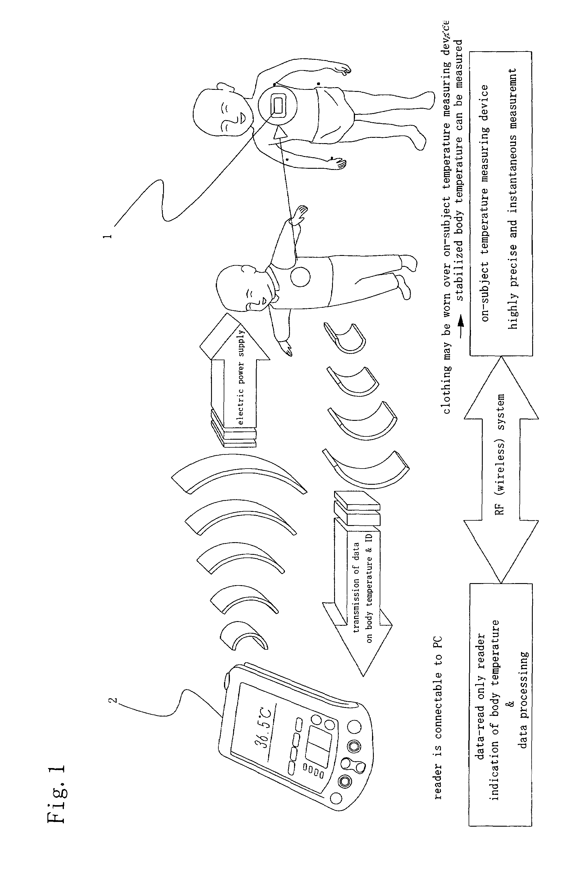
[0063]FIG. 1 is an overall schematic view of a temperature measuring system to which a first embodiment of the temperature measuring device according to the present invention is applied.

[0064]Referring to FIG. 1, an on-subject temperature measuring device 1 as a temperature measuring device, which is attached to a subject when a temperature of the subject is measured, receives a radio wave from a reader 2 as an external device and is thereby electrically powered. By means of the electric power, temperature measurement is performed in the on-subject temperature measuring device 1. The results of the measurement are transmitted through radio waves to the reader 2 as a temperature of the subject and ID data. The reader 2 is so constructed as to be connectable to a personal computer (not shown), and data processing by the personal computer is performed according to need.

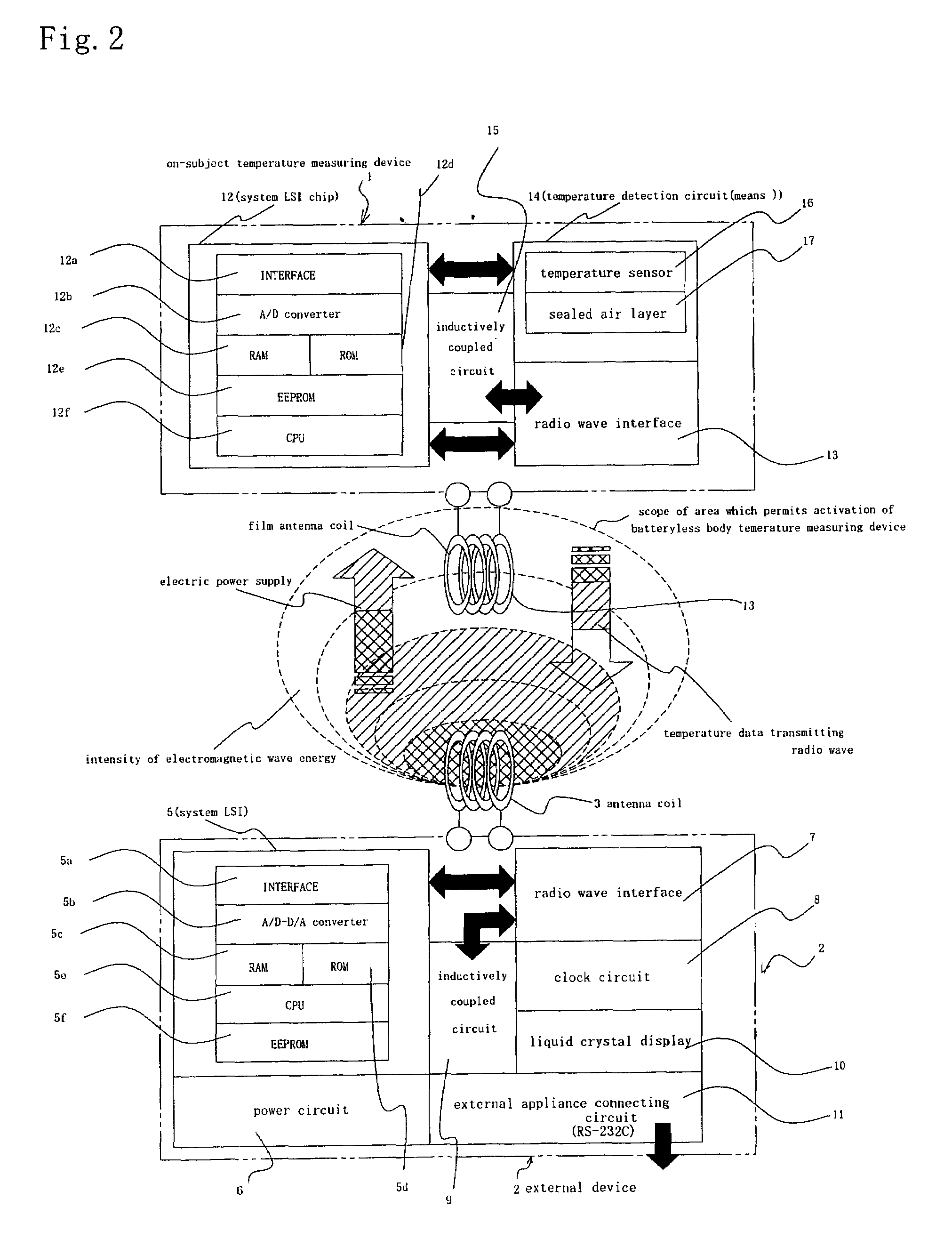
[0065]FIG. 2 is an overall schematic view schematically representing the temperature measuring system, to which the fi...

second embodiment

[0103]In a temperature measuring system to which a second embodiment of the temperature measuring device according to the present invention is applied, a circuit element of an on-subject temperature measuring device 1 comprises no CPU or A / D converter, as different from the first embodiment. Instead thereof, an oscillation circuit is provided for producing oscillations with frequencies proportional to resistance values of a chip thermistor or film type thermistor, and a radio wave with such an oscillation frequency or a period (pulse width) of the frequency is directly transmitted as data to a reader 2 as an external device, and the frequency or period is converted into temperature data by a software in the external device. In this embodiment, the circuitry is simplified. This enables the temperature measuring system to be one to which such an inexpensive temperature measuring device is applied.

third embodiment

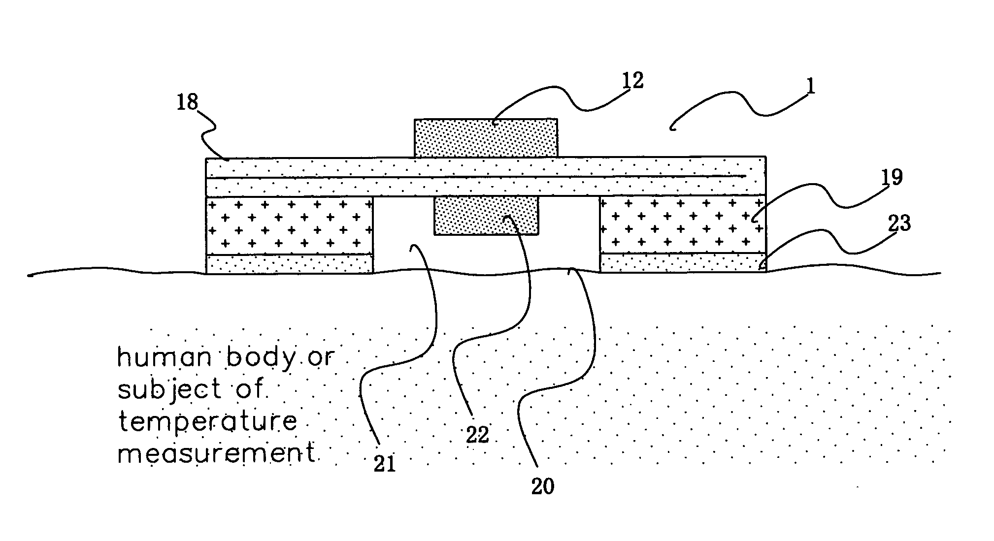
[0104]FIG. 15 is a bottom view of a third embodiment of the on-subject temperature measuring device according to the present invention. FIG. 16 is a bottom view of another form of the third embodiment of the temperature measuring device according to the present invention. FIG. 17 is still another form of the third embodiment of the temperature measuring device according to the present invention. Difference between the third embodiment and the first embodiment resides in that a sheet 24 with an adhesive is used in the third embodiment of the temperature measuring device, and the sheet 24 with an adhesive is applied to a nonwoven fabric 19 which is attached to a film-form control substrate 18, and a space within an opening 20 of the nonwoven fabric 19 is thereby sealed as shown in the FIGS. In the form shown in FIG. 15, a rectangular air communication hole 25 is provided at a predetermined position of the sheet 24 with an adhesive. The air communication hole 25 may be circular. In the...


PUM

PropertyMeasurementUnit
temperatureaaaaaaaaaa
flexibleaaaaaaaaaa
thicknessaaaaaaaaaa

Abstract

A temperature measuring device and a temperature measuring method are provided which are capable of obtaining precise measured temperature values with respect even to old persons, sucklings or infants, which device may be formed into a disposable type according to need, which method may be carried out using such a disposable type device according to need, and which enable precise temperature measurement in real time. An on-subject temperature measuring device 1, which is attached to a subject when a temperature of the subject is measured, receives a radio wave from a reader 2 as an external device and is thereby electrically powered. Using the electric power, temperature measurement is performed in the on-subject temperature measuring device 1. The results of the measurement are transmitted through radio waves to the reader 2 in the form of a temperature of the subject and ID data. The reader 2 is so constructed as to be connectable to a personal computer (not shown), and data processing by the personal computer is performed according to need.

Description

TECHNICAL FIELD[0001]The present invention relates to a temperature measuring device which is preliminarily attached to a surface of a subject of temperature measurement to carry out temperature measurement. In particular, it relates to a temperature measuring device and a temperature detecting method which, if a subject of temperature measurement is for example a human body, are capable of instantaneously and precisely measuring a temperature from the outside of clothing on the human body.BACKGROUND ART[0002]In relation to a shape of a temperature detecting part of an electronic thermometer, for example, there has been proposed in Japanese Unexamined Patent Publication No. 133030 / 1988 an electronic thermometer which is attachable to a body surface and has a discoidal shape. However, a temperature detecting part which has been practically used generally has a rod-like shape, and measurement of body temperatures has been conducted by holding or inserting such a temperature detecting ...

Claims


Application Information

Patent Timeline
Patent Type & Authority Patents(United States)
IPC IPC(8): G01K1/00G01K7/00G08C17/02G01K1/14G01K1/02G01K15/00G08C17/00G08C19/00
CPCG01K1/024G01K15/00G01K2215/00G01K1/02G01K1/14G01K7/00G08C17/02
Inventor SAKANO, MOTOYA
Owner SAKANO KAZUHITO
Why Eureka
Try Eureka