Connection device with a cable gland having housing parts enabling relative movement therebetween

a technology of connecting device and housing, which is applied in the direction of coupling device connection, optical elements, instruments, etc., can solve the problems of hindering the axial movement capacity of the plug housing, which is necessary for unlocking the plug, and can only be used very conditionally in a rough industrial environment. , to achieve the effect of simple mounting and dismounting capacity

Inactive Publication Date: 2008-04-15
PHOENIX CONTACT GMBH & CO KG
View PDF3 Cites 33 Cited by
  • Summary
  • Abstract
  • Description
  • Claims
  • Application Information

AI Technical Summary

Benefits of technology

[0010]A primary object of this invention is therefore to provide a connection device of the initially described type which enables both reliable mechanical protection of the plug and of the cable to be connected, and also provides a simple mounting and dismounting capacity of the plug with a corresponding socket.
[0011]This object is achieved in the initially described connection device according to a first teaching of the invention in that the housing is made in two parts, specifically a first housing part for holding the plug and a second housing part for connection to the cable gland which has a union nut, that the end of the first housing part assigned to the second housing part has a connecting area which is made such that the first housing part can be connected to the second housing part and can be axially moved in the connected state, on the second housing part there being at least one stop and on the first housing part at least one opposing stop so that the second housing part and the first housing part can be moved axially relative to one another by a defined path.

Problems solved by technology

However, the disadvantage here is that the known standard fiber-optic plugs can only be used very conditionally in a rough industrial environment.
However, the problem in the known connection device is that the desired safe and strong holding of the plug and of the optical fiber to be connected in the housing, especially the fixing of the optical fiber which is necessary for sealing by means of the cable gland, hinders the axial movement capacity of the plug housing which is necessary for unlocking the plug.

Method used


Image

  • Connection device with a cable gland having housing parts enabling relative movement therebetween
  • Connection device with a cable gland having housing parts enabling relative movement therebetween
  • Connection device with a cable gland having housing parts enabling relative movement therebetween

Examples


first embodiment

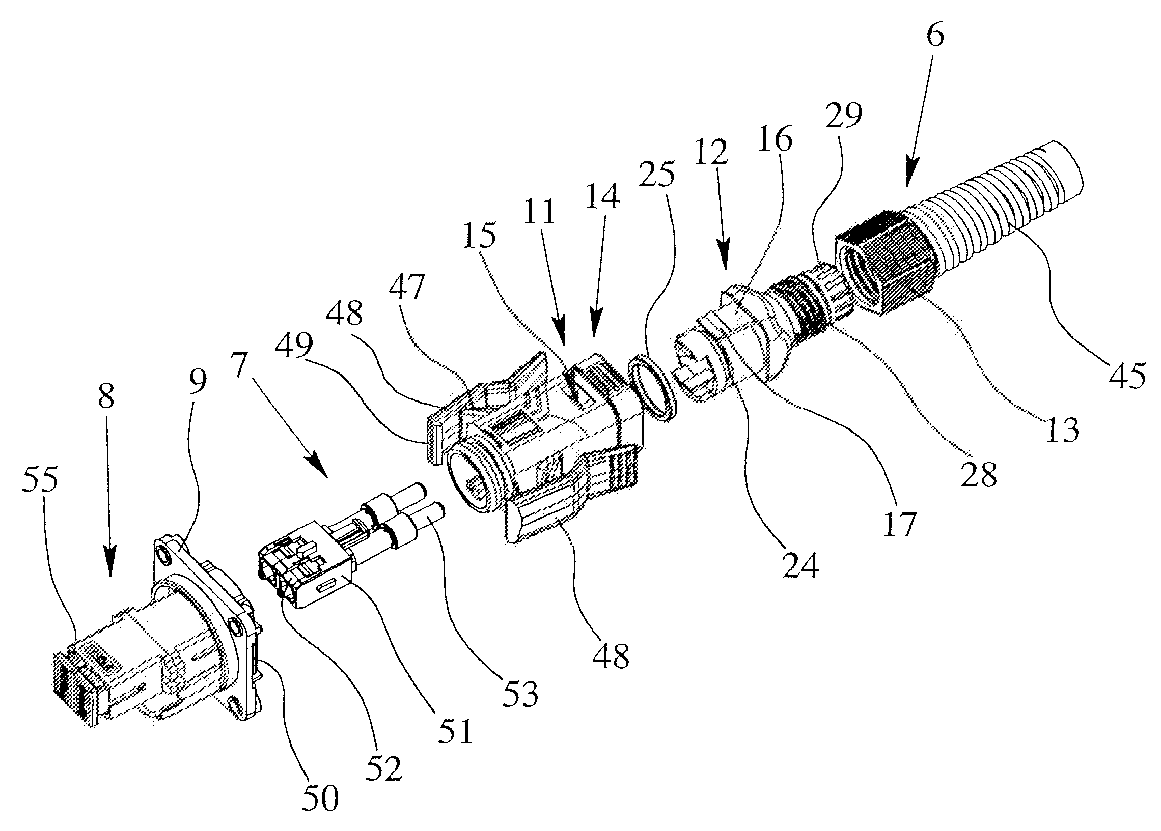
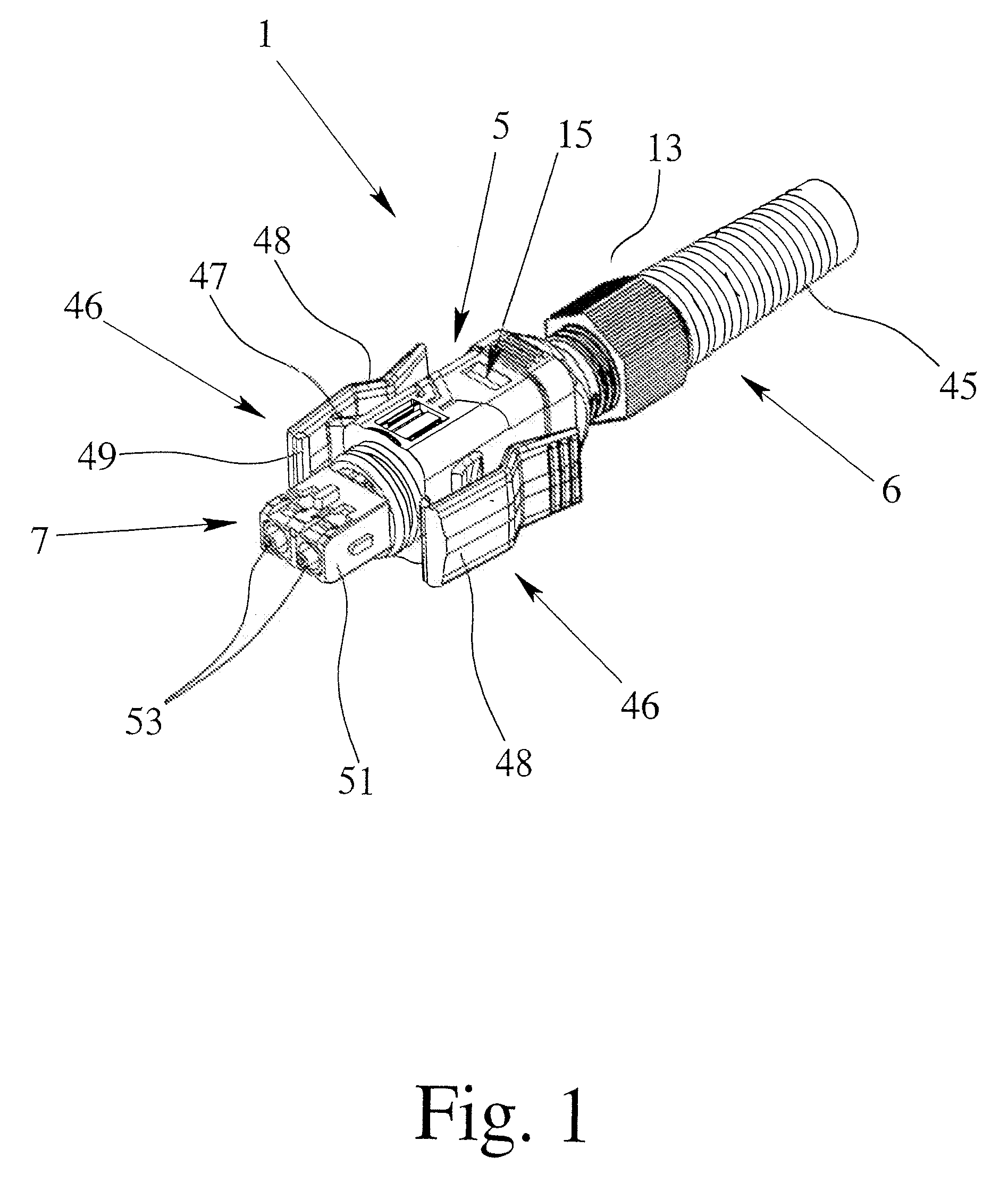
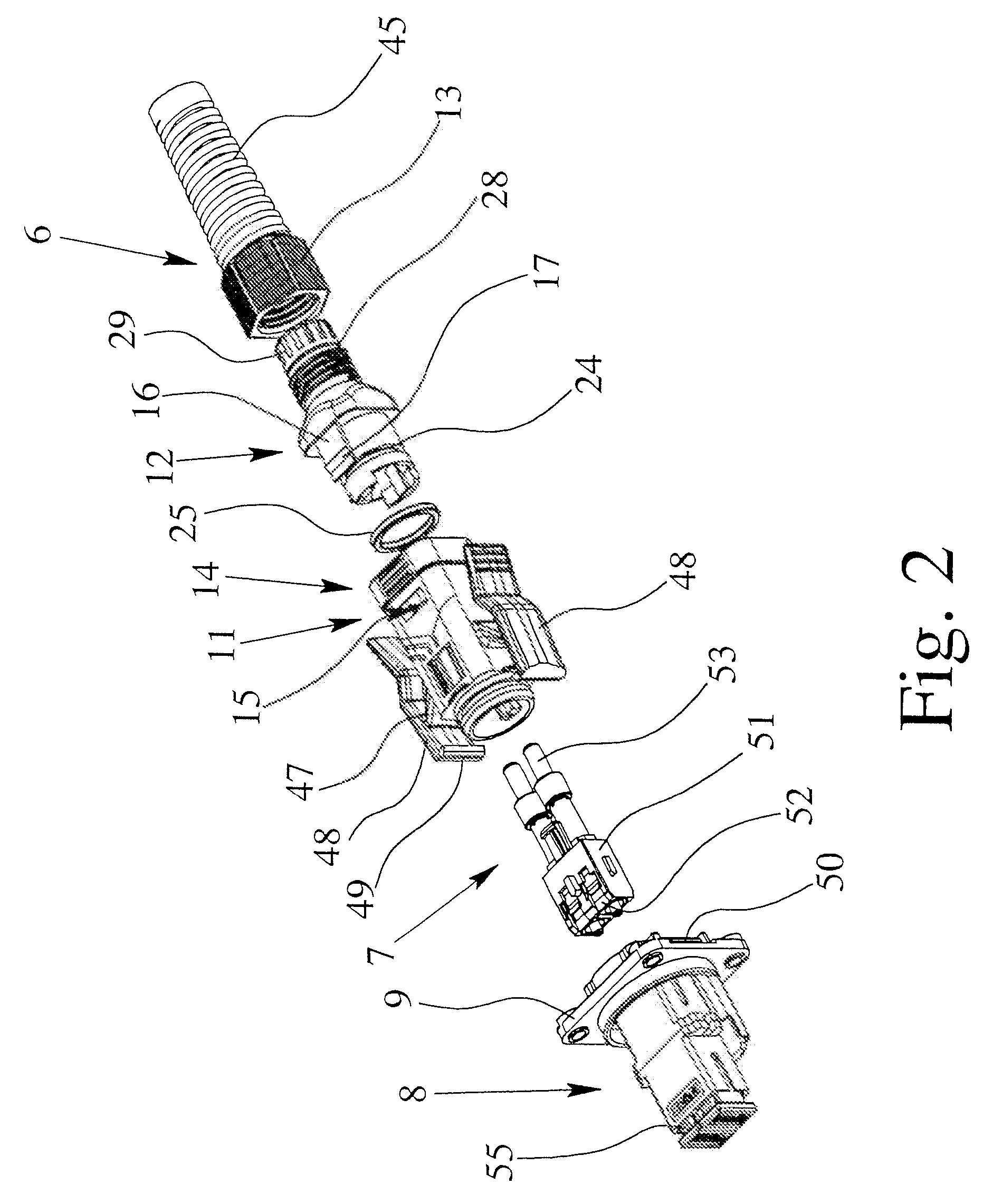
[0036]In the connection device 1 of the invention, which is shown in FIGS. 1 to 4, the housing 5 has a first housing part 11 for holding the plug 7 and a second housing part 12 for connection to the cable gland 6 which has a union nut 13. The housing 5 is thus made in two parts, as is apparent especially from FIG. 2. In this connection, the first housing part 11 has a connecting area 14 which is made such that the first housing part 11 can be locked to the second housing part 12. However, in this connection, it is important that the locking between the first housing part 11 and the second housing part 12 is made such that axial displacement of the first housing part 11 relative to the second housing part 12 is possible, the axial displacement however being limited.

[0037]In this connection, in the connecting area 14 of the first housing part 11, a window 15 is formed which, in the mounted state of the first housing part 11 and the second housing part 12, is engaged by a projection 17...

second embodiment

[0042]the connection device 1 shown in FIGS. 5 to 7, likewise, has a housing 5, a cable gland 6 and a plug 7 for connection of the fibers of the optical fibers 3, 4 of the fiber-optic cable 2. However, in contrast to the above described embodiment, here, it is not the housing 5, but the cable gland 6 which is made in two parts. The cable gland 6, in addition to the union nut 13, has a sleeve-shaped part 31 with an outside thread 32 onto which the union nut 13 can be screwed. In terms of its external shape, the sleeve-shaped part 31 is similar to the cable-side end of the second housing part 12 as shown in FIGS. 1 to 4.

[0043]The end of the housing 5 assigned to the cable gland 6, in turn, has a connecting area 33 which is shaped differently and which is made such that the sleeve-shaped part 31 can, on the one hand, be locked to the connecting area 33, but on the other, can be moved axially to a limited degree.

[0044]For this purpose, several recesses 34 are formed in the sleeve-shaped...


PUM


Abstract

A connection device for connecting an optical fiber to an electrical device has a housing, a cable gland, and a plug for insertion into the corresponding socket of the electrical device, the housing having a cable passage for insertion of the optical fiber, the plug being held at least partially in the housing and being connectable to the fibers of the optical fiber which has been inserted into the cable passage. The housing has a first housing part for holding the plug and a second housing part for connection to the cable gland. The first and second housing parts are connectable in a manner enabling them to be axially moved relative to each other in the connected state by an extent defined by at least one stop on the second housing part that is engageable with at least one opposing stop on the first housing part.

Description

BACKGROUND OF THE INVENTION[0001]1. Field of the Invention[0002]The invention relates to a connection device for connecting a cable, especially an optical fiber, to an electrical device, with a housing, a cable gland, and a plug for insertion into the corresponding socket of the electrical device, the housing having a cable passage for insertion and routing of the cable, the plug being held at least partially in the housing, and being connectable to the fibers or cores of the cable which has been inserted into the cable passage.[0003]2. Description of Related Art[0004]Connection devices for connecting a cable to an electrical device, especially to a communications means, for example, a computer, a notebook or a telephone, are known from practice. The cable is easily connected to the electrical device by the cable being connected to a plug and this plug being inserted into a corresponding socket on the electrical device. In order to simplify connection of the cable to the electrical ...

Claims


Application Information

Patent Timeline
Patent Type & Authority Patents(United States)
IPC IPC(8): G02B6/38
CPCG02B6/3887G02B6/4292G02B6/389G02B6/4219G02B6/3893G02B6/38875
Inventor FELDNER, RALF
Owner PHOENIX CONTACT GMBH & CO KG
Why Eureka
Try Eureka