AI technical title is built by Patsnap AI team. It summarizes the technical point description of the patent document.
a technology of crimping contacts and communication jacks, which is applied in the direction of coupling device details, coupling device connections, printed circuit aspects, etc., can solve the problems of increasing problems such as crosstalk between capacitive and inductive couplings of closely spaced parallel conductors within the jack and/or plugs
Active Publication Date: 2008-04-15
PANDUIT
View PDF22 Cites 62 Cited by
Summary
Abstract
Description
Claims
Application Information
AI Technical Summary
This helps you quickly interpret patents by identifying the three key elements:
Problems solved by technology
Method used
Benefits of technology
Benefits of technology
[0002]The present invention relates generally to electrical connectors, and more particularly, to a communication jack having crimped contacts secured to a flexible printed circuit.
Problems solved by technology
In the communications industry, as data transmission rates have steadily increased, crosstalk due to capacitive and inductive couplings among the closely spaced parallel conductors within the jack and / or plug has become increasingly problematic.
Method used
Image
Click on the blue label to locate the original text in one second.
Reading with bidirectional positioning of images and text.
Examples
Embodiment Construction
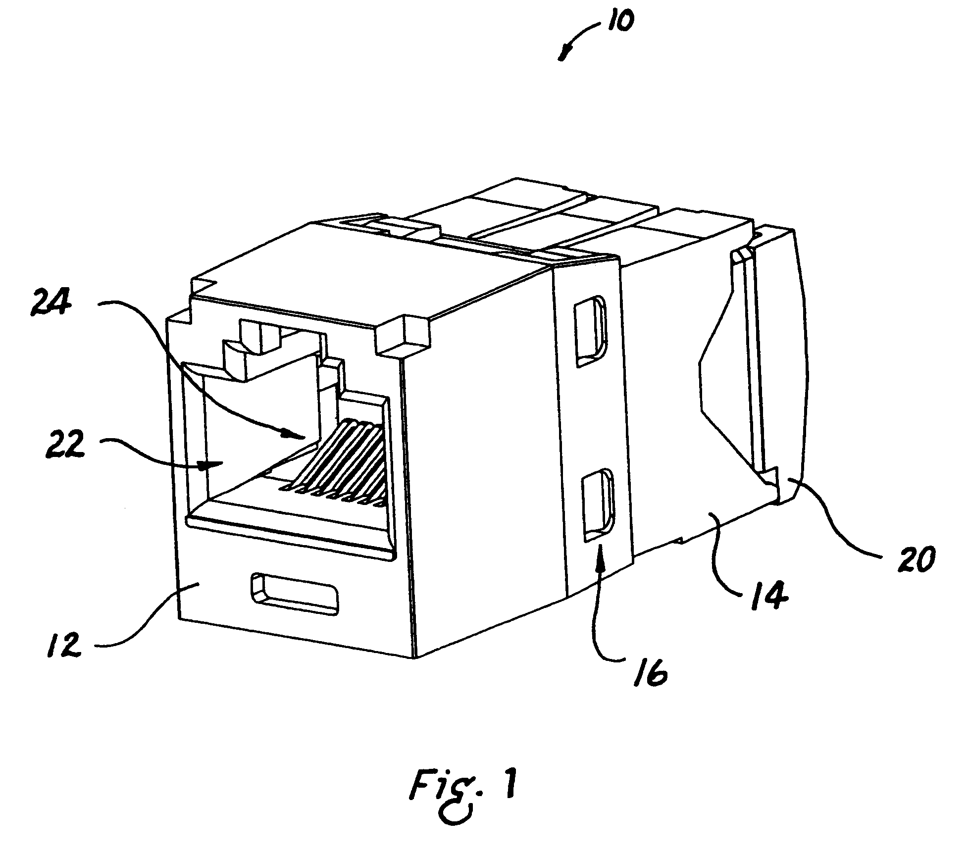
[0005]FIG. 1 is a front perspective view of a communications jack;
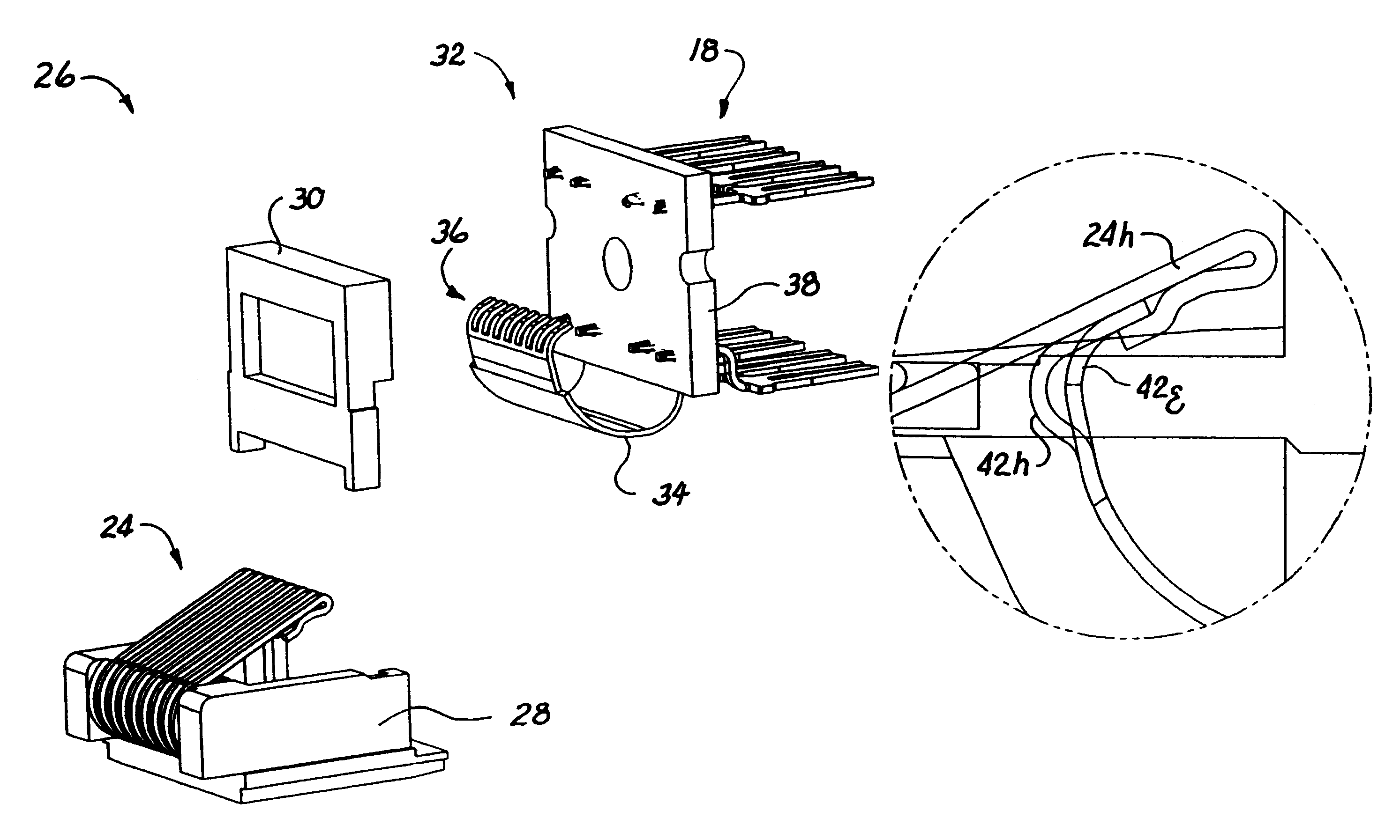
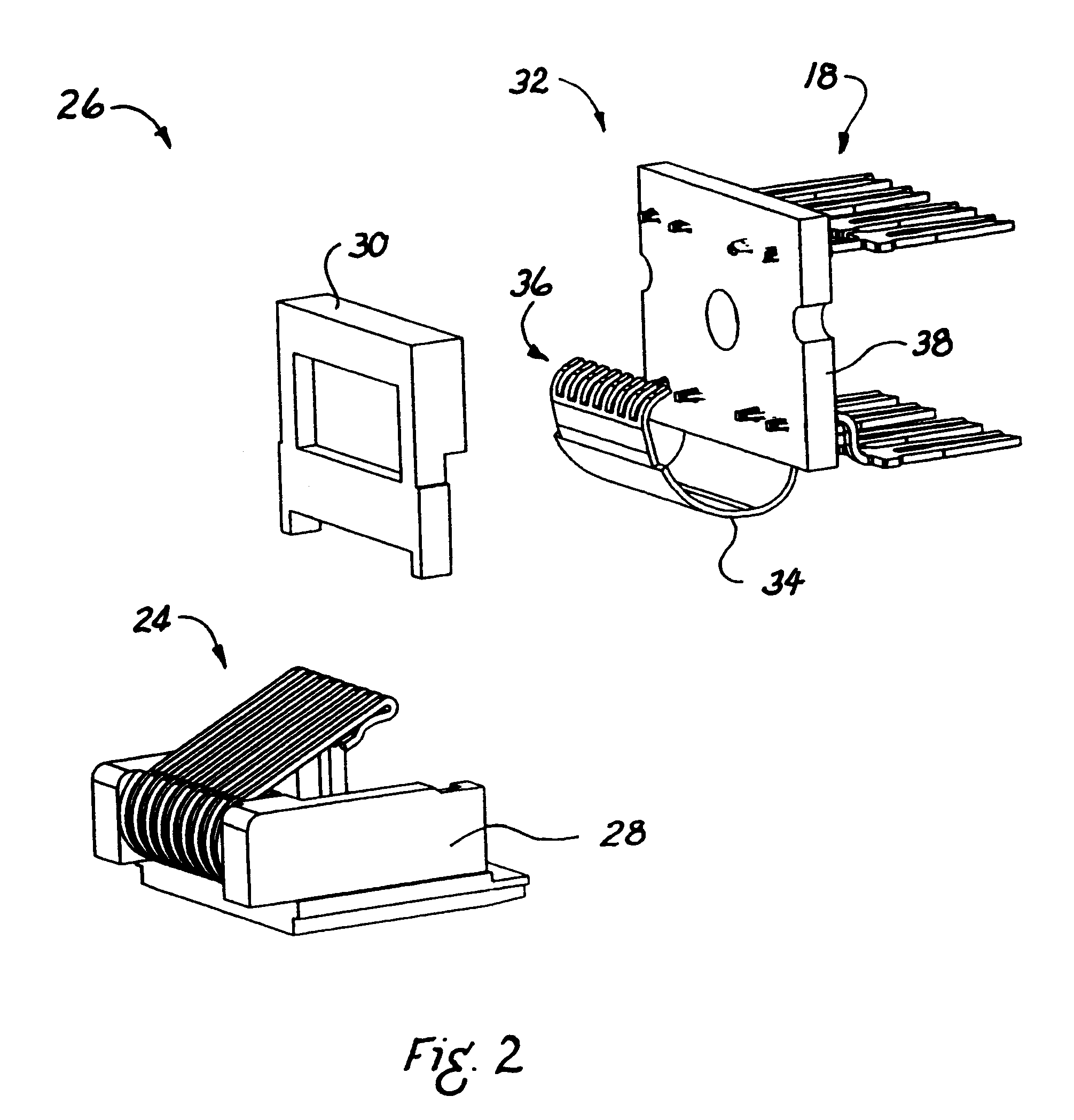
[0006]FIG. 2 is an exploded perspective view of a contact assembly showing the use of a printed circuit board having a flexible portion;
[0007]FIG. 3 is a plan view of a flexible portion of a printed circuit board;
[0008]FIG. 4 is a perspective view of an upper conductive trace of the flexible portion of FIG. 3;
[0009]FIG. 5 is a perspective view of a lower conductive trace of the flexible portion of FIG. 3;
[0010]FIG. 6 is a cross-sectional view along the line 6-6 of FIG. 3;
[0011]FIG. 7 is a cross-sectional view along the line 7-7 of FIG. 3;
[0012]FIG. 8 is a plan view of a printed circuit board showing a flexible portion and a rigid portion;
[0013]FIG. 9 is a diagram showing a side view and a plan view of jack contact points of a flexible portion of a printed circuit, with first and eighth connection extensions shown in extended positions;
[0014]FIG. 10 is a diagram showing a side view and a plan view of jack contact point...
PUM
Abstract
A communications connector with a flexible printed circuit board is provided. The flexible printed circuit board is electronically and mechanically connected to the plug interface contacts of the jack near the plug / jack interface, in order to provide effective crosstalk compensation. The flexible printed circuit board has fingers at one end allowing it to flex as individual plug interface contacts are depressed when a plug is installed into the jack. The flexible printed circuit board, or a flexible portion of a printed circuit board, is provided with elongated extensions for certain conductors to accommodate the connection of six-contact or eight-contact plugs to the connector.
Description
CROSS-REFERENCE TO RELATED APPLICATIONS[0001]This application claims the benefit of U.S. Provisional Patent Application No. 60 / 699,823 filed Jul. 15, 2005. This application incorporates by reference in their entireties U.S. patent application Ser. No. 11 / 014,097, filed Dec. 15, 2004; U.S. patent application Ser. No. 11 / 055,344, filed Feb. 20, 2005; U.S. patent application Ser. No. 11 / 078,816, filed Mar. 11, 2005; U.S. patent application Ser. No. 11 / 099,110, filed Apr. 5, 2005; U.S. Provisional Application No. 60 / 587,416, filed Jul. 13, 2004; U.S. Provisional Application No. 60 / 637,024, filed Dec. 17, 2004.FIELD OF THE INVENTION[0002]The present invention relates generally to electrical connectors, and more particularly, to a communication jack having crimped contacts secured to a flexible printed circuit.BACKGROUND OF THE INVENTION[0003]In the communications industry, as data transmission rates have steadily increased, crosstalk due to capacitive and inductive couplings among the cl...
Claims
Application Information
Patent Timeline
Application Date:The date an application was filed.
Publication Date:The date a patent or application was officially published.
First Publication Date:The earliest publication date of a patent with the same application number.
Issue Date:Publication date of the patent grant document.
PCT Entry Date:The Entry date of PCT National Phase.
Estimated Expiry Date:The statutory expiry date of a patent right according to the Patent Law, and it is the longest term of protection that the patent right can achieve without the termination of the patent right due to other reasons(Term extension factor has been taken into account ).
Invalid Date:Actual expiry date is based on effective date or publication date of legal transaction data of invalid patent.

