Method to stabilize a moving image

a moving image and image technology, applied in the field of methods of stabilizing an image, can solve the problems of subject's eye moving, eye being observed through the confocal microscope by the ophthalmologist is not necessarily stable or stationary, and difficulty in interpretation of observed images

Inactive Publication Date: 2008-04-15
BOARD OF SUPERVISORS OF LOUISIANA STATE UNIV & AGRI & MECHANICAL COLLEGE ON BEHALF OF THE LOUISIANA STATE UNIV HEALTH SCI CENT OFFICE OF THE VICE CHANCELLOR FOR ACADEMIC AFFAIRS +1
View PDF12 Cites 37 Cited by
  • Summary
  • Abstract
  • Description
  • Claims
  • Application Information

AI Technical Summary

Problems solved by technology

However, the eye being observed through the confocal microscope by the ophthalmologist is not necessarily stable or stationary.
The subject's eye may move due to the inability of the subject to maintain a totally steady gaze, or due to movements of the subject causing the subject's eyes to move in the observed field.
These types of movements make the interpretation of the observed images difficult.
Even “minor” movements can become a significant problem as the microscope will magnify the image of the movement.
However

Method used


Image

  • Method to stabilize a moving image
  • Method to stabilize a moving image
  • Method to stabilize a moving image

Examples


first embodiment

I FIRST EMBODIMENT

A 1-D Signal Representation

A.1 Image Capturing

[0048]The raw unstabilized confocal videos are obtained at the rate of 29 frames / sec. Although theoretically one can extract and process 29 frames from a one-second long video, it is not desirable for the following reasons:[0049](1) The drifting or destabilization of objects in these frames may not be prominent in subsequent frames, and performing a computational stabilization procedure on subsequent frames is not an efficient use of resources.[0050](2) Experiments have shown that the stabilization technique employed on adjacent subsequent frames is more susceptible to Gaussian or white noise.

[0051]For these reasons, it is more efficient to depopulate the sampled frames. The sample rate should be fine enough to keep the presentation displayed on the monitor from jittering due to too coarse depopulation. The actual depopulation can vary with the application, and one acceptable rate was to depopulate the frame date set by...

second embodiment

II SECOND EMBODIMENT

Using a 2-D Signal

[0109]This embodiment is similar to that of the 1-D signal embodiment, and the description will concentrate on the differences between the two embodiments.

A.1 In this embodiment, the steps of Image Capturing (A.1) is identical to the 1-D embodiment. Frame data may be depopulated as needed.

A.2 The signal synthesis step in this embodiment is lacking as this embodiment retains the 2-D image as the working signal.

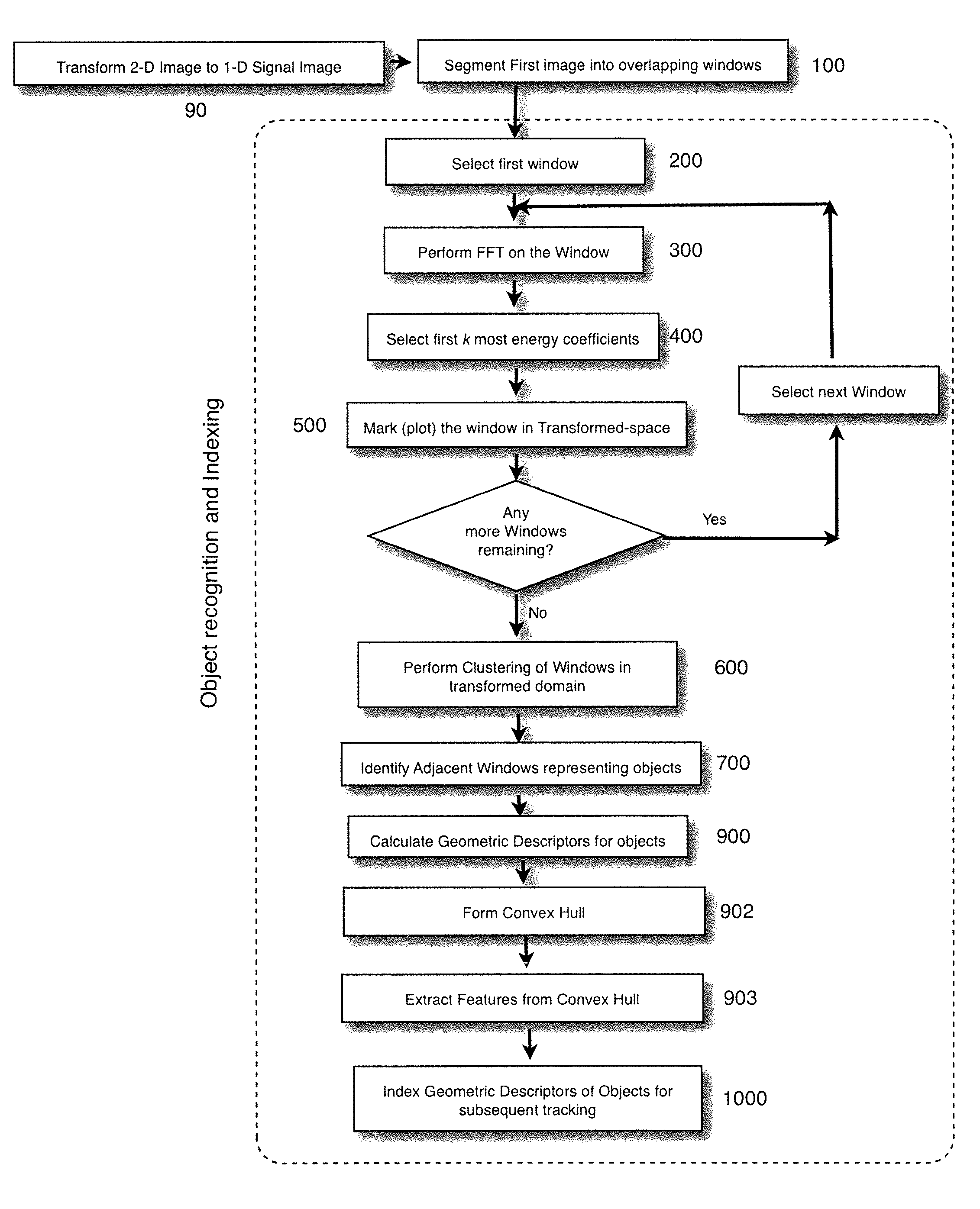
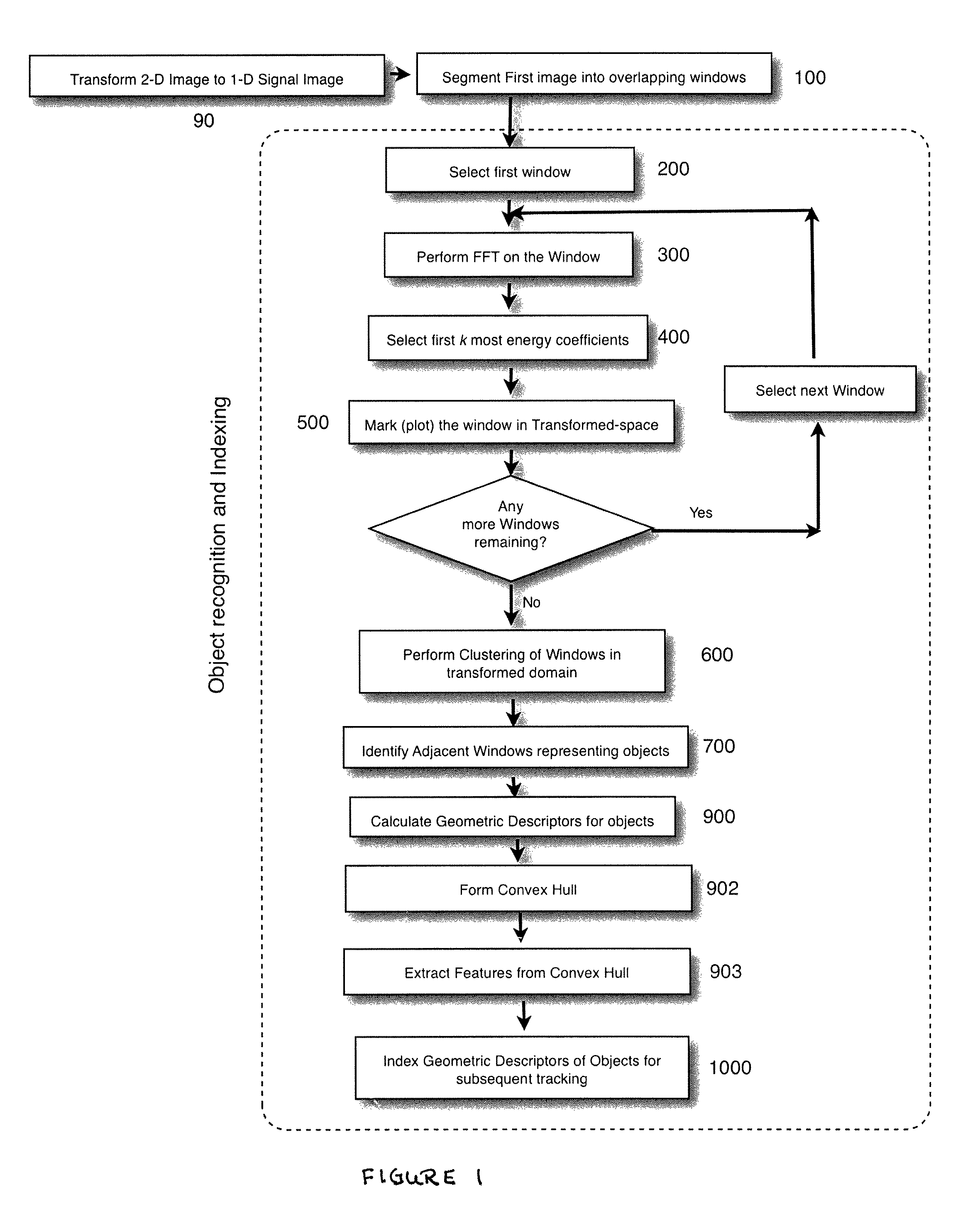
A.3 Signal Partition

[0110]For each frame, partition the frame into overlapping 2 dimensional windows (step 100FIG. 1), where the windows are aligned along a path through the frame. For instance, one embodiment utilized the following horizontally orientated path for traversing the frame (a type of zig zag):

[0111]

In this embodiment, an 8×8 pixel window was utilized with adjacent windows having an overlap of 5 pixels with the proceeding window, where the overlap is in the direction of movement along the path through the frame, hence, it is not...


PUM


Abstract

The invention is a process to compare two digital images (and usually more) and to identify objects in each image. After object identification, object descriptors are formed. The object descriptors of the objects in one frame are compared to those of objects in the second frame, allowing the tracking of an object in the two frames. The movement of each tracked object within the two frames is quantified, and the second frame is corrected to account for the object's movement.

Description

COMPUTER PROGRAM LISTING APPENDIX[0001]Attached hereto and incorporated by reference is the computer program listing appendices. The appendices, in accordance with 37 CFR 1.96, are contained on a single compact disk, submitted in duplicate. Each disk submitted has two folders: (1) Window based image stabilization; and (2) Zig-Zag based image stabilization.[0002]A directory of each folder follows:[0003]Zig-Zag based image stabilization:Createdsize and name of filesFeb. 19, 200307:51 AM2,426class_mers.mFeb. 19, 200307:51 AM5,041c_cluster.mFeb. 19, 200307:51 AM334c_fft.mFeb. 28, 200303:49 PM1,741c_main.mFeb. 19, 200307:51 AM7,508c_mer.mJun. 07, 200310:34 AM18,029image_comparison.mMar. 03, 200303:10 PM1,359kmeans.mMar. 22, 200304:54 PM2,916main_script.mFeb. 27, 200304:38 PM264mark_p.mFeb. 19, 200307:51 AM1,851p_file3.m[0004]Window based image stabilization:Createdsize and name of filesJun. 07, 200310:34 AM18,029Image_comparison.mMar. 03, 200303:10 PM1,359kmeans.mJul. 01, 200304:49 PM24,...

Claims


Application Information

Patent Timeline
IPC IPC(8): G06K9/40
CPCG06K9/50G06T5/003G06T5/50A61B3/1025A61B3/13A61B5/0068A61B5/7257G02B21/367G06T2207/10056G06T2207/20021G06T2207/20056G06T2207/30041G06T2207/20201G06V10/421
Inventor DUA, SUMEETBEUERMAN, ROGER W.
Owner BOARD OF SUPERVISORS OF LOUISIANA STATE UNIV & AGRI & MECHANICAL COLLEGE ON BEHALF OF THE LOUISIANA STATE UNIV HEALTH SCI CENT OFFICE OF THE VICE CHANCELLOR FOR ACADEMIC AFFAIRS
Why Eureka
Try Eureka