Method of verifying proper installation of a zoned HVAC system

a hvac system and installation method technology, applied in the field of method of verifying can solve the problems of installation difficulty, installation difficulty, and inability to verify proper installation of a zoned hvac system

Active Publication Date: 2008-04-22
CARRIER CORP
View PDF9 Cites 168 Cited by
  • Summary
  • Abstract
  • Description
  • Claims
  • Application Information

AI Technical Summary

Problems solved by technology

Otherwise, the zoning system cannot operate properly and maintain desired comfort in all zones.
However, if such a wiring error is made, the comfort problem may not be immediately apparent.
An installer has no easy way to verify proper installation without waiting for the right set of conditions to develop.
This method does verify if the damper is operating, but it does not verify if it is responding to the correct sensor.

Method used


Image

  • Method of verifying proper installation of a zoned HVAC system
  • Method of verifying proper installation of a zoned HVAC system
  • Method of verifying proper installation of a zoned HVAC system

Examples


Embodiment Construction

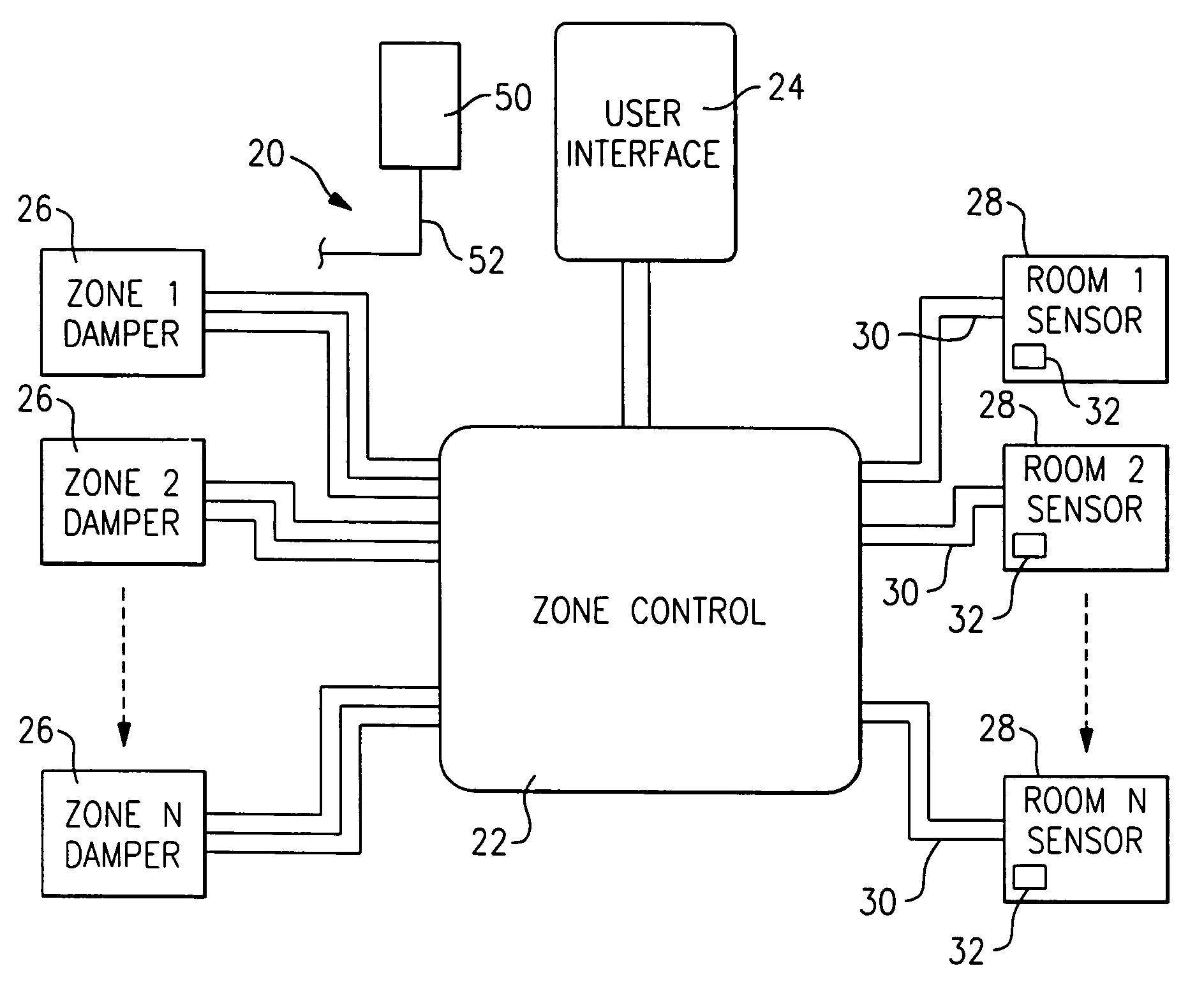
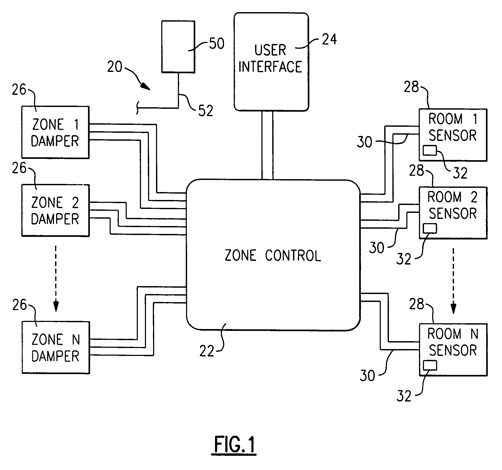
[0014]A portion of an HVAC system 20 is illustrated in FIG. 1 having a zone control 22 for operating a plurality of dampers 26 associated with each of several zones, and for receiving control information from a plurality of sensors 28 associated with the same plurality of zones. As shown, wires 30 connect the sensors to the zone control 22, and the sensors 28 are illustrated as “smart sensors” each having inputs 32 to allow an operator to set a desired temperature set point, or otherwise provide a signal to the control 22, and ultimately a system control 24. Most preferably, the communication between the various components 26, 28, 24 and 22 is by digital serial communication over control wires such as is disclosed in co-pending U.S. patent application Ser. No. 10 / 752,626, entitled “Serial Communicating HVAC System,” filed Jan. 7, 2004, the entire disclosure of which is incorporated herein by reference.

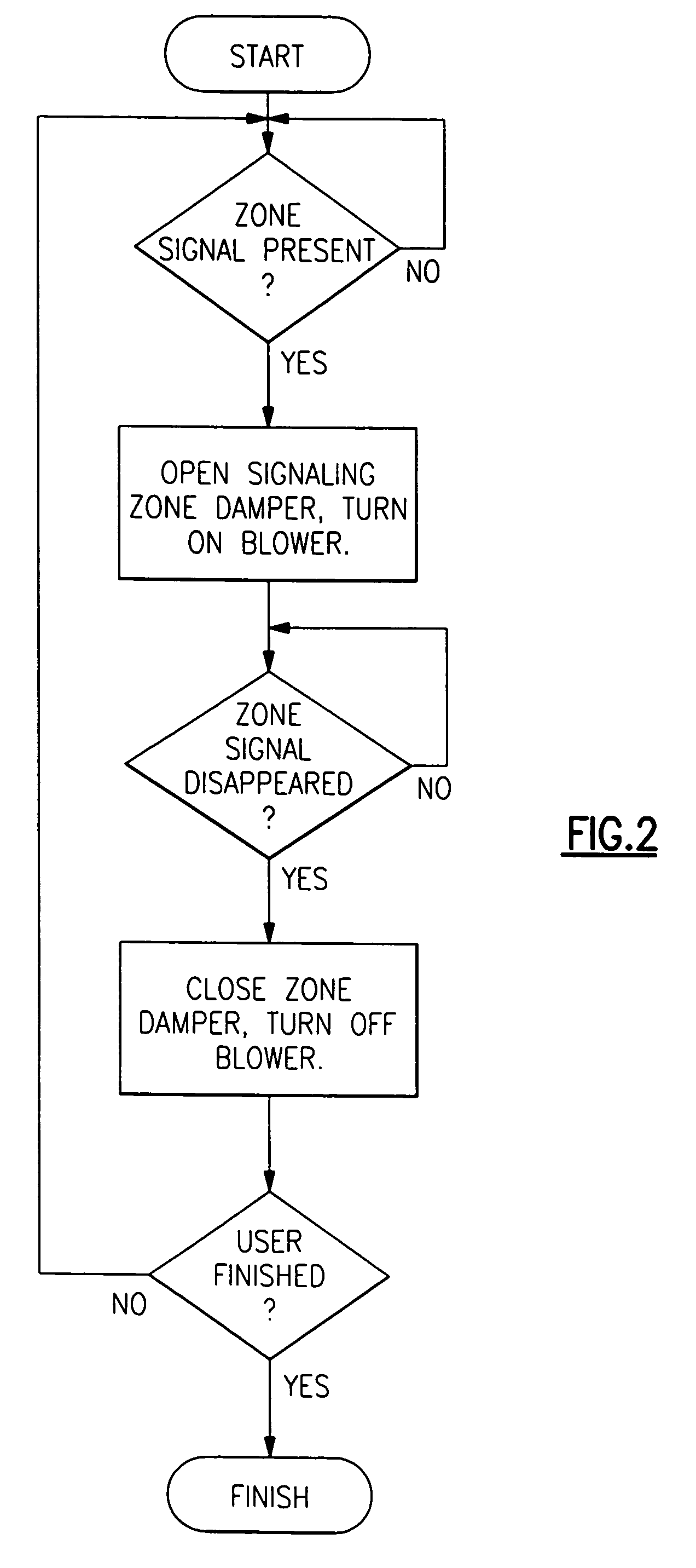
[0015]As shown in the flowchart of FIG. 2, once the system 20 is initially install...


PUM


Abstract

A method and control is provided wherein the sensors in a plurality of zones are properly associated with the dampers associated for each of the zones after installation. A technician goes to each zone and sends a signal from the sensor, and the control then makes a change at the associated damper. The technician can then ensure the two are properly associated within the control.

Description

[0001]This application claims priority to provisional patent application Ser. No. 60 / 537,760, filed Jan. 20, 2004, and entitled “Method of Verifying Proper Installation of a Zoned HVAC System.” The disclosure of this provisional application is incorporated herein in its entirety, by reference.BACKGROUND OF THE INVENTION[0002]This application relates to a method of verifying that the sensors disposed in a plurality of zones in a multi-zone heating, ventilating and air conditioning (HVAC) system are properly associated with corresponding zone dampers.[0003]In a typical ducted HVAC system, a blower in an indoor air handler circulates air to various parts of the home through a system of ducts. In a typical zoned HVAC system, the ducts are divided into several zones, one for each part of the building that is desired to be controlled independently of the other areas. A set of dampers is installed into the ducts, with at least one damper for each zone. These dampers can be opened or closed...

Claims


Application Information

Patent Timeline
Patent Type & Authority Patents(United States)
IPC IPC(8): F25B49/00F24F3/00F25D17/02F24F11/00
CPCF24F11/0086F24F11/30F24F11/49F24F11/88G05D23/19
Inventor SHAH, RAJENDRA K.PURANEN, CHRISTOPHER M.
Owner CARRIER CORP
Why Eureka
Try Eureka