Inkjet printer

a technology of inkjet printer and inkjet head, which is applied in the direction of printing, etc., can solve the problem of unstable ink ejection property of inkjet head

Active Publication Date: 2008-04-22
BROTHER KOGYO KK
View PDF19 Cites 9 Cited by
  • Summary
  • Abstract
  • Description
  • Claims
  • Application Information

AI Technical Summary

Benefits of technology

[0007]The present invention is advantageous in that an improved inkjet printer is provided, in which frothing of ink in a sub-tank due to ruffle of the ink can be suppressed.
[0010]In the inkjet printer configured as above, the partition wall extending perpendicularly to the reciprocating direction can effectively prevent the ink in the ink storing space from being significantly agitated. Thus, the ink does not froth up in the movable ink tank and hence does not entrain bubbles thereinto. The bubbles may make the ink ejection property of the inkjet head unstable.

Problems solved by technology

The bubbles may make the ink ejection property of the inkjet head unstable.

Method used


Image

  • Inkjet printer
  • Inkjet printer
  • Inkjet printer

Examples


Embodiment Construction

[0038]Hereinafter, an embodiment of the present invention will be described with reference to the accompanying drawings.

[0039]Configuration of the Printer

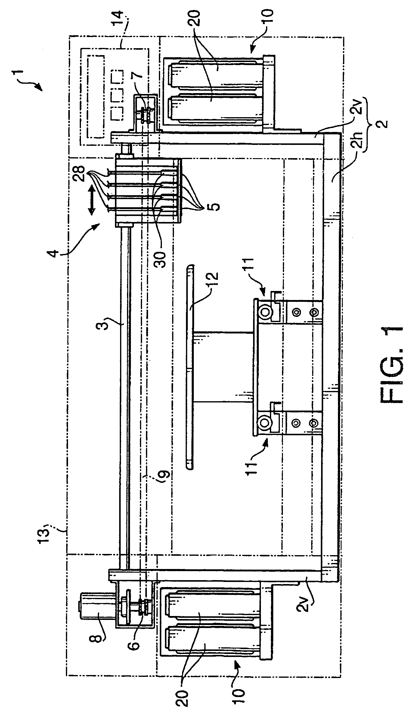
[0040]FIG. 1 schematically illustrates a configuration of an inkjet printer 1 according to an embodiment of the invention. As shown in FIG. 1, the inkjet printer 1 includes a frame 2 provided on a casing (which is schematically illustrated by chain double-dashed lines). The frame 2 includes a horizontal portion 2h disposed on the bottom of the inkjet printer 1 and vertical portions 2v extending perpendicularly to and upward from both sides of the horizontal portion 2h.

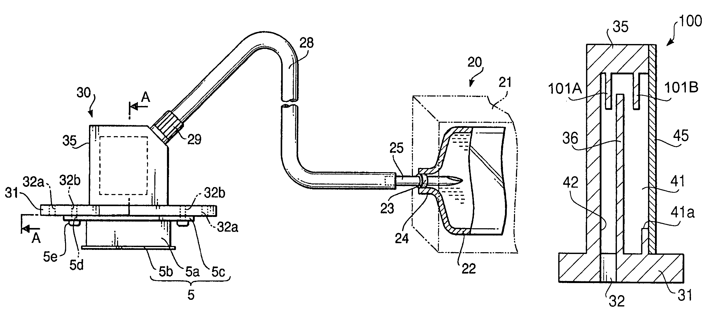
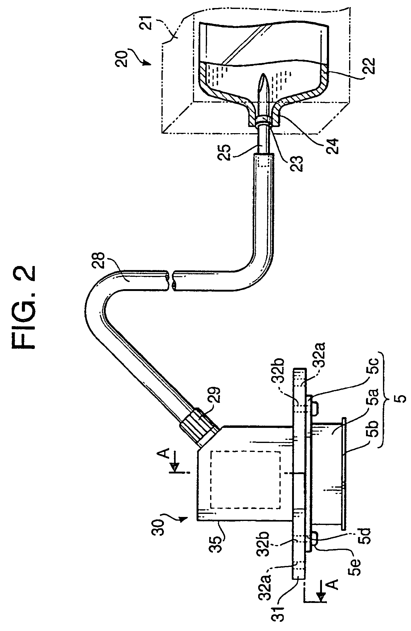
[0041]A slide rail 3 is horizontally supported by the vertical portions 2v to extend between the upper ends of the vertical portions 2v. A carriage 4 is mounted on the slide rail 3 slidably in a longitudinal direction of the slide rail 3, or a main scanning direction of the inkjet printer 1. Four piezoelectric inkjet heads 5 are mounted on an undersurface of the carr...


PUM


Abstract

An inkjet printer includes an inkjet head that ejects ink onto a recording medium, a movable ink tank having an ink introducing opening, an ink storing space for storing ink introduced through the ink introducing opening, and an ink discharging opening for discharging the ink of the ink storing space into the inkjet head, and a carriage that supports the inkjet head and the movable ink tank and reciprocates in a direction perpendicular to a feeding direction of the recording medium. The movable ink tank includes a partition wall extending in a direction perpendicular to a reciprocating direction of the carriage to divide the ink storing space into multiple rooms being in fluid communication with each other at upper portions thereof.

Description

BACKGROUND OF THE INVENTION[0001]The present invention relates to an inkjet printer that ejects ink on a recording medium to print an image thereon.[0002]Conventionally, a so-called serial type inkjet printer has been known. In the serial type inkjet printer, an inkjet head is mounted on a carriage that reciprocates in a direction perpendicular to a feeding direction of a recording sheet (i.e., in a width direction of the recording sheet). A tube is connected to the inkjet head for supplying ink from an ink supplying source to the inkjet head. When an image is printer using such a serial type inkjet head, when the carriage changes its moving direction, a large acceleration acts on the inkjet head and the ink inside the tube, which connects the inkjet head with the ink supplying source. The acceleration generates dynamic pressure in the ink within the tube.[0003]Some inkjet head is provided with a sub-tank, which is also mounted on the carriage. When the sub-tank is provided, the ink...

Claims


Application Information

Patent Timeline
Patent Type & Authority Patents(United States)
IPC IPC(8): B41J2/175
CPCB41J2/17509B41J2/17513B41J2/17556B41J2/17566
Inventor IKEZAKI, YOSHIYUKIHYAKUDOME, TAKAO
Owner BROTHER KOGYO KK
Why Eureka
Try Eureka