

Golf club shaft
a golf club and shaft technology, applied in the field of golf clubs, can solve the problems of difficulty in swinging, unfavorable directional stability of the head, and difficulty in disposing the center of gravity of the golf club at a low position, so as to increase or decrease the number of layers of the prepreg, and reduce the ratio eit/eib
Active Publication Date: 2008-04-22
SUMITOMO RUBBER IND LTD
View PDF15 Cites 29 Cited by
- Summary
- Abstract
- Description
- Claims
- Application Information
AI Technical Summary
Benefits of technology
[0018]When the golf club has the above-described construction and the head thereof is heavy, i.e., when the weight of the head is not less than 190 g, it is possible to secure the degree of freedom in designing the center of gravity of the head by appropriately setting the thickness of the head in various regions of the head. Thereby the center of gravity of the head can be disposed at a low position.
[0059]As described above, according to the present invention, since the weight of the head of the golf club is set to not less than 190 g, the head can be designed to have its center of gravity at a low position thereof. Therefore the ball can be hit at a high drive angle and thereby the flight distance thereof can be increased. Further even though a heavy large head is mounted on the shaft, the front side of the shaft does not deform too much. Therefore the ball hit with the golf club is favorable in the directional stability, and the golfer does not have a feeling that the weight of the head is amplified, thus being able to swing and handle the golf club easily.
Problems solved by technology
Thus in designing the head, it is difficult to dispose the center of gravity thereof at a low position.
That is, the directional stability of the head is unfavorable.
In addition, a user feels that the head is too heavy, thus having difficulty in swinging it.
Thus when a heavy head is mounted on the shaft, the deformation amount of the shaft at its front side is so large that the orbit of the head is unstable during a swing, and thus the directional stability of the hit ball is unfavorable.
Further the user feels that the head is heavy because the weight of the head is amplified by the flexing of the shaft, thus having difficulty in swinging the golf club because it is heavy.
Method used
View moreImage
Smart ImageViewing Examples

Examples
example 1
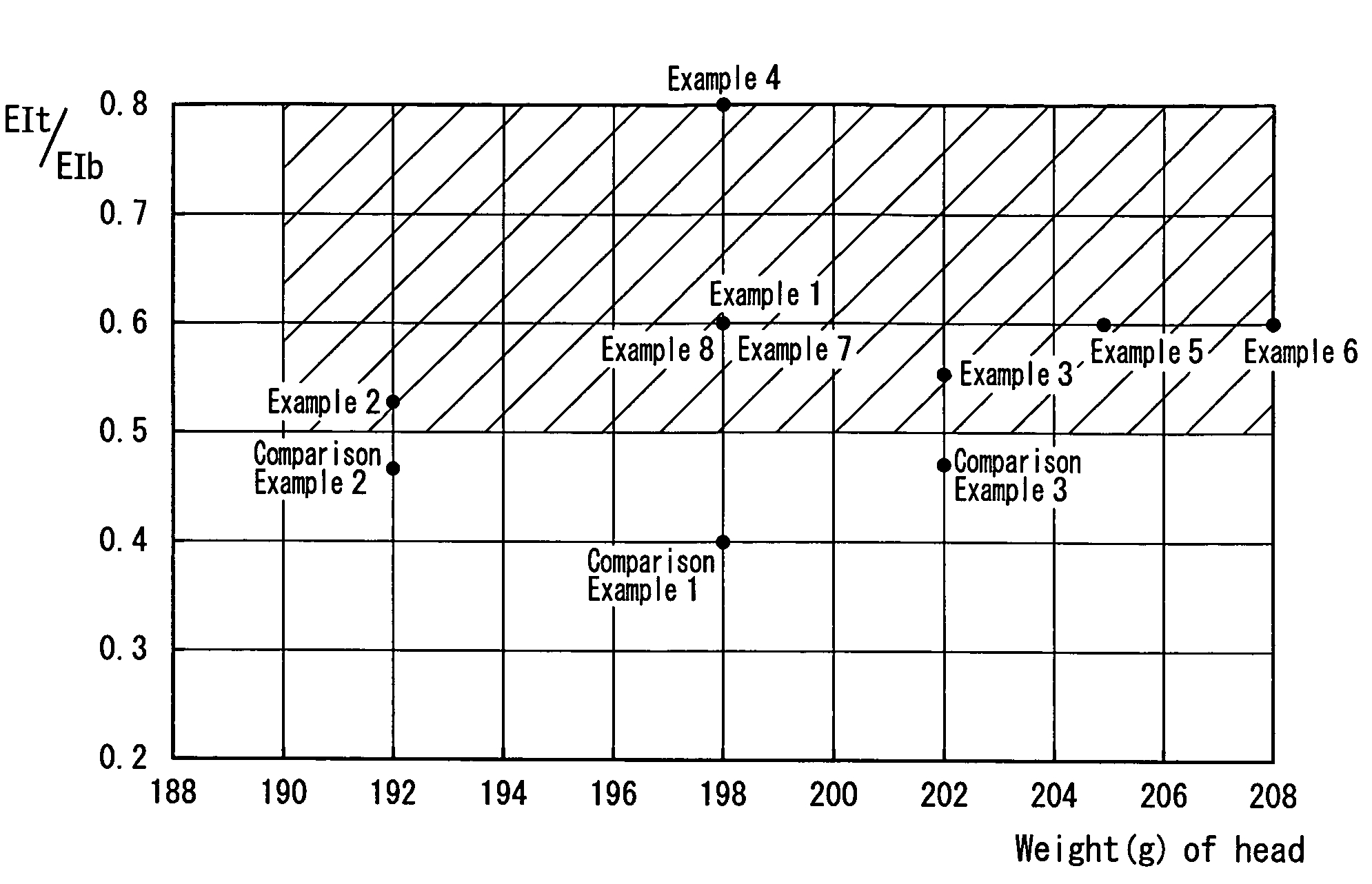
[0086]The golf club of the example 1 had the same construction as that of the golf club of the first embodiment. More specifically, the weight of the head was 198 g. The ratio EIt / EIb was set to 0.60. The rigidity value EIt was set to 3.0×10⁶ kgf·mm2.
example 2
[0087]The weight of the head was set to 192 g. The value of the ratio EIt / EIb was set to 0.52. The rigidity value EIt was set to 2.5×10⁶ kgf·mm2.
example 3
[0088]The weight of the head was set to 202 g. The value of the ratio EIt / EIb was set to 0.55. The rigidity value EIt was set to 2.5×10⁶ kgf·mm2.
Login to View More PUM
 Abstract
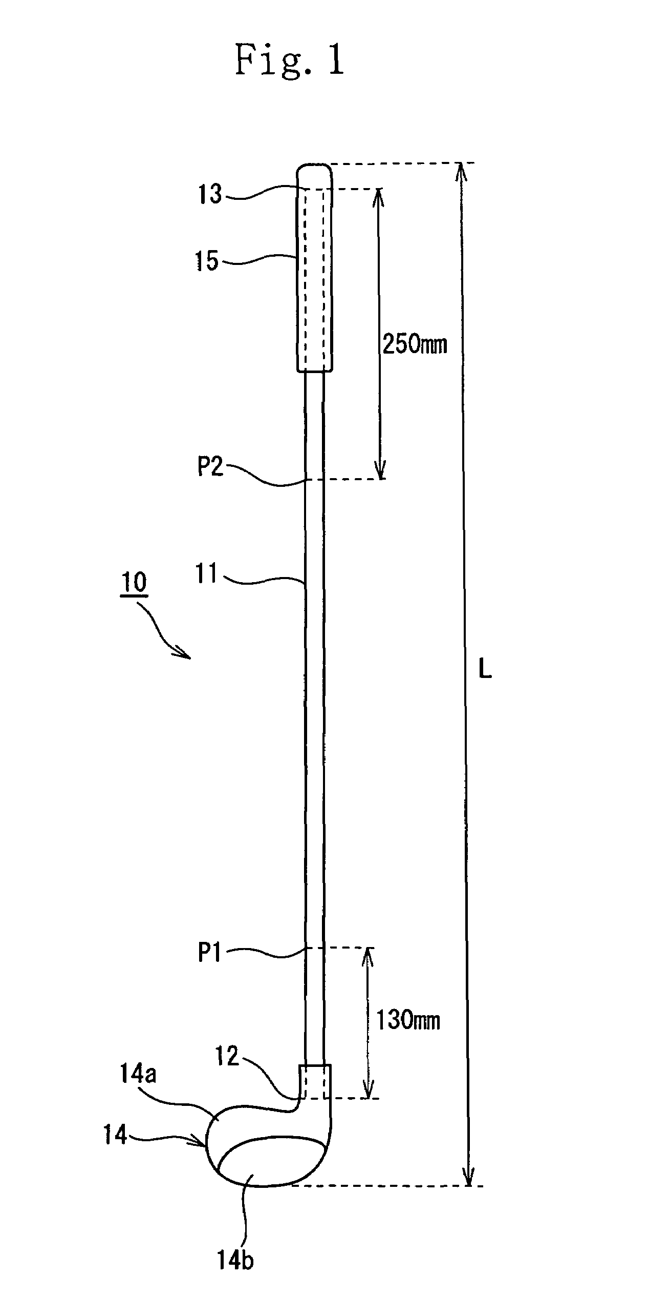
A wood golf club (10) which is not less than 44 inches in a length thereof and whose head (14) is not less than 190 g in a weight thereof. The value of a ratio of a rigidity value EIt at a position spaced at an interval of 130 mm from a head-side front end of a shaft (11) of the golf club (10) to a rigidity value EIb at a position spaced at an interval of 250 mm from a grip-side rear end of the shaft (11) is set to not less than 0.50.
Description
[0001]This nonprovisional application claims priority under 35 U.S.C. § 119(a) on Patent Application No(s). 2004-291303 filed in Japan on Oct. 4, 2004, the entire contents of which are hereby incorporated by reference.FIELD OF THE INVENTION[0002]The present invention relates to a golf club. More particularly, the present invention relates to a golf club in which a wood head can be designed to have its center of gravity at a low position thereof.DESCRIPTION OF THE RELATED ART[0003]To hit a golf ball (hereinafter often referred to as ball) a long distance with the golf club, in the conventional art, there is a tendency of designing the head having a high repulsive force. But the regulation on the repulsion of the head was issued, based on the amendment to the rule of the golf club made by the joint statement on the joint plan for “Effect of Spring” published by R & A (Royal and Ancient Golf Club of St. Andrews) and USGA (United States Golf Association) on May 9, 2002. Thereby the tend...
Claims
Login to View More Application Information
Patent Timeline
 Patent Type & AuthorityPatents(United States)
IPC IPC(8): A63B53/00A63B53/10A63B53/04A63B102/32
CPCA63B53/00A63B53/10A63B59/0014A63B2209/023A63B2209/026A63B60/06A63B60/08A63B60/10A63B60/00
InventorOYAMA, HITOSHI
OwnerSUMITOMO RUBBER IND LTD