Apparatus and method for duobinary transmission

a duobinary and optical technology, applied in the field of duobinary transmission, can solve the problems of degrading the quality of the signal at the output of the transmitter, degrading the back-to-back performance of the filtered duobinary transmitter, and affecting the transmission efficiency of the transmitter,

Inactive Publication Date: 2008-04-22
LUCENT TECH INC
View PDF4 Cites 5 Cited by
  • Summary
  • Abstract
  • Description
  • Claims
  • Application Information

AI Technical Summary

Benefits of technology

[0011]One aspect of the invention provides an optical duobinary transmitter comprising a precoder, an amplifier coupled to the precoder, and a low bandwidth Mach-Zehnder modulator coupled to the amplifier having a bandwidth of less than about 60% of the transmission bit rate of the transmitter. The modulator is adapted to provide low pass filtering for low pass filtered duobinary transmission in an optical fiber transmission system having residual dis

Problems solved by technology

Significant deviations from this ideal response, in bandwidth and/or response ripple, tend to seriously degrade the quality of the signal at the output of the transmitter.
Reflections between the electrical filter and modulator, for example, can seriously degrade the back-to-back performance of a filtered duobinary transmitter.
Such stringent transmitter specifications tend to substantially increase transmitter component costs.
Accordingly, relaxing these constraints on system architecture would significantly improve transmitter cost and yield.
However, such a device response is not realistic for practical devices or for higher bit rate (e.g. ˜10 Gb/s) applications.
The use of a modulator with a sinc magnitude response has a monotonic decrease in the quality of the data pattern with an increase in residual dispersion.
Therefore, the sinc response modulator creates a data pattern that is not as robust against accumulated dispersion within a transmission link.
Specifically,

Method used


Image

  • Apparatus and method for duobinary transmission
  • Apparatus and method for duobinary transmission
  • Apparatus and method for duobinary transmission

Examples


Embodiment Construction

[0021]The present invention provides an apparatus and method for transmitting optical duobinary signals, which allow for relaxed response requirements and fabrication tolerances for an optical duobinary transmitter for duobinary transmission across transmission links having residual dispersion. Residual dispersion as used herein refers to dispersion accumulated in a transmission link up to a point just prior to a receiver.

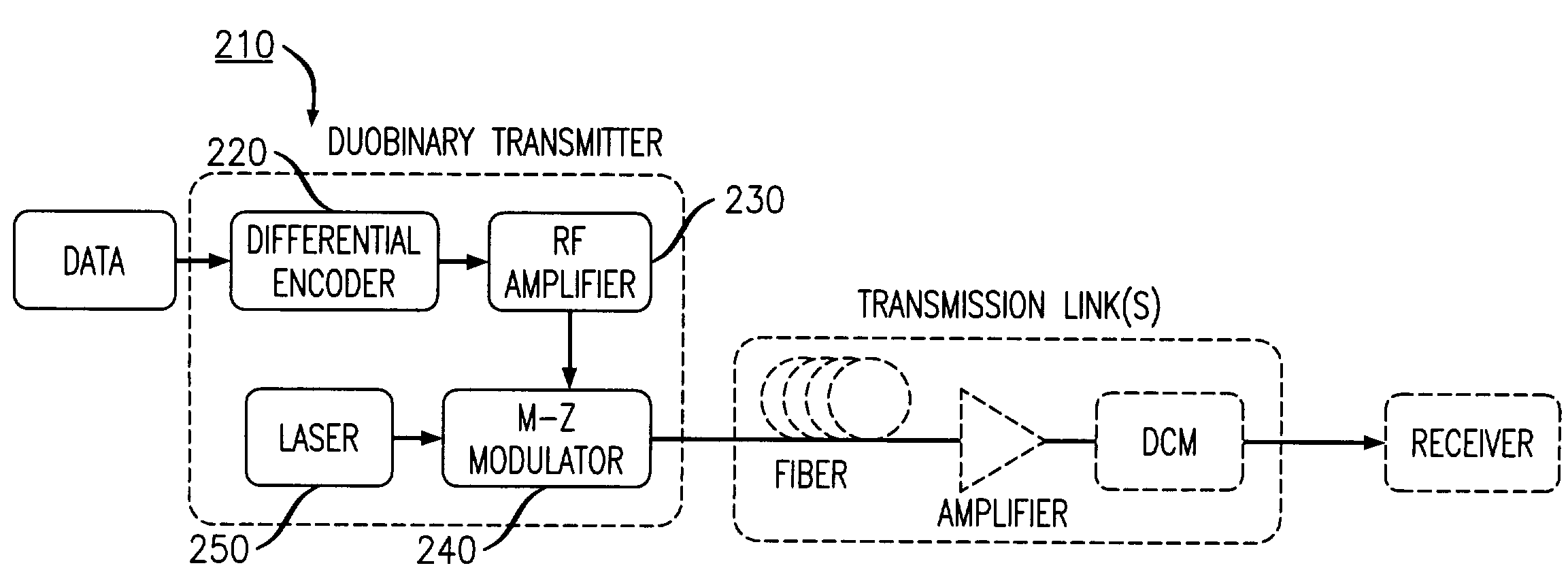
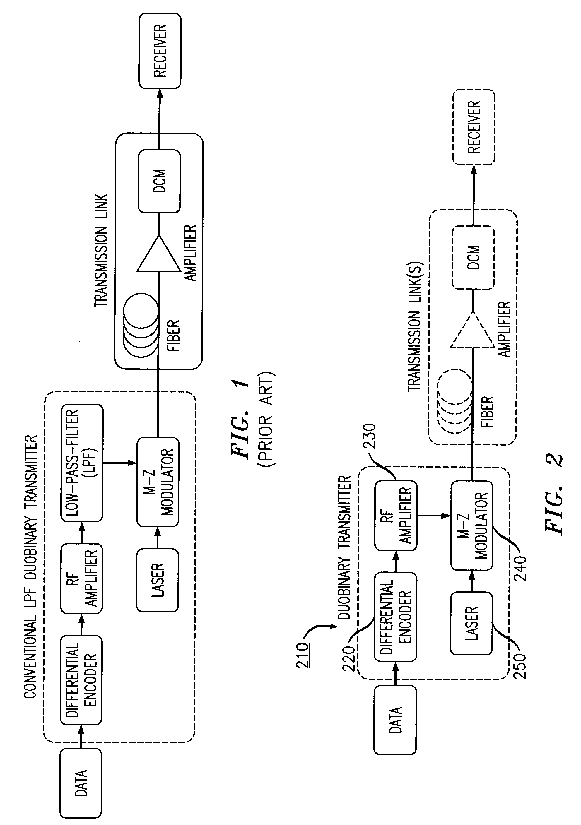
[0022]In one preferred embodiment of the invention, shown in FIG. 2, a duobinary transmitter 210 is provided which includes a differential encoder 220, an RF amplifier 230, a Mach-Zehnder modulator 240, and a laser 250.

[0023]As shown in FIG. 2, the transmitter 210 may be coupled to one or more transmission links and a receiver. ‘Transmission links’ as used herein, refers to transmission apparatus or system components between a transmitter and a receiver that are necessary or appropriate for a desired application. Such components include but are not limited to trans...


PUM


Abstract

An apparatus and method are provided for transmitting an optical duobinary signal using a low bandwidth modulator having a bandwidth of less than about 60% of the transmission bit rate of the transmitter. The modulator is adapted to provide low pass filtering for low pass filtered duobinary transmission in an optical fiber transmission system having residual dispersion.

Description

REFERENCE TO RELATED APPLICATION[0001]This application relates to a co-pending application entitled “Duobinary Transmission System And Method” filed even date herewith and is hereby incorporated by reference.FIELD OF THE INVENTION[0002]The present invention relates generally to duobinary transmission and, more particularly, to low pass filtered optical duobinary transmission.BACKGROUND OF THE INVENTION[0003]Optical duobinary transmission is a well-known modulation format in fiber optic communications. The duobinary transmission format is potentially a cost effective commercial fiber optic data transport solution, particularly for metropolitan applications. Characteristics that help make duobinary transmission potentially cost effective include a high tolerance to accumulated and / or residual dispersion, flexible requirements with respect to the placement of dispersion compensation units within a transmission system, a high tolerance to nonlinear penalty, and relatively low bandwidth ...

Claims


Application Information

Patent Timeline
IPC IPC(8): H04B10/12H04B10/04H04B10/155
CPCH04B10/505H04B10/508
Inventor GILL, DOUGLAS M.LEVY, DAVID S.LIU, XIANGTAYAHI, MONCEF B.WEI, XING
Owner LUCENT TECH INC
Why Eureka
Try Eureka