
Radio access point testing method and testing apparatus

a radio access point and testing method technology, applied in the direction of transmitter monitoring, receiver monitoring, transmission monitoring, etc., can solve the problems of difficult detection of especially the radio interface portion of the radio access point apparatus, difficult to immediately judge damage, communication impossible,

Inactive Publication Date: 2008-04-29
HITACHI LTD
View PDF17 Cites 30 Cited by
  • Summary
  • Abstract
  • Description
  • Claims
  • Application Information

AI Technical Summary

Benefits of technology

[0024]In view of the above circumstances, the present invention has for its object to realize a radio access point testing method and apparatus which permit the normality verification and radio characteristics test of a radio communication system even during the operation of the system. Another object of the invention is to provide a radio access point testing method and apparatus which can comprehensively test various failures. Still another object of the invention is to execute a test without interrupting an offered communication service. A further object of the invention is to provide a method and an apparatus which can execute a test in a desired access point and sector on-line.

Problems solved by technology

Regarding failure detection means for the system, the failure of especially the radio interface portion of the radio access point apparatus is difficult of detection because of the uncertain interface of the very radio channel.
By way of example, in a case where the antenna of the radio access point apparatus has damaged, it is difficult to immediately judge the damage as the failure of the radio access point apparatus, even at the cutoff of the communication with the user access terminal.
On this occasion, such various causes are considered that the particular user will not actually exist in the cell, and that an interference wave will exist in a radio zone connected with the user access terminal, to make the communication impossible.
With the first prior-art example explained above, the antenna failure can be detected, but receiver defects cannot be detected.
Another problem is that, in case of a reception-only antenna or the like, an antenna failure cannot be detected.
However, in a case where a radio reverse link has any abnormality, the maintenance engineer cannot hear the recorded voice.
Also, in a case where a radio forward link has any abnormality, he / she cannot hear the vocal message.
With the second prior-art example explained above, the normality of the access-point radio apparatus can be verified, but an antenna failure cannot be detected.
Another problem is that the verifiable normality is merely the propriety of communication, and that a radio characteristics change, such as the degradation of a reception performance attendant upon a failure of slight degree, cannot be quantitatively decided.
Patent Document 4, however, contains nothing about a normality test for communication and discloses an abnormality detecting method for the receiver.
The bestowal of redundant setups on all the access point apparatuses increases a system constructing cost, and drastically spoils economy.
Nevertheless, when the service is interrupted by any failure, a service quality lowers for users, and also a business company offering the service suffers the drawback of being incapable of accounting, so that the service interruption ascribable to the occurrence of the failure must be avoided to the utmost.
Since, however, the interface between user access terminals and a radio access point is a radio channel in the mobile communication system, a communication quality changes depending upon an environment which surrounds a mobile access point or a fixed access point, and it is very difficult to decide whether an inferior communication quality is ascribable to the apparatus failure or the surrounding environment.
When an interference wave from the radio access point of the other system is inputted, it becomes difficult to detect a reception signal from the mobile access terminal of the pertinent system.
On the other hand, the phenomenon is considered to be ascribable to the failure of the radio access point apparatus.
The first failure example is an antenna failure.
The second failure example is a receiver failure.
By way of example, when one receiver has undergone the failure in an access terminal which implements diversity reception by installing a plurality of receivers, a reception performance degrades.
The third failure example is a transmitter failure.
It is considered that the signal quality of reverse links will have degraded due to the transmitter failure of the access point, and that access terminals will communicate with the neighboring access point of good signal quality, resulting in the decrease of the number of connected access terminals.
In this manner, in the mobile communication system, the same phenomena as in the failure occurrences (for example, the small number of connected access terminals) may highly possibly be observed in spite of the normal operation of the system itself, and various causes are considered for the failures, so that the failure detection is very difficult.
When it is intended to detect the above failure examples by the prior-art failure detection means, problems as stated below are involved.
Accordingly, this technique cannot detect the case of a failure which permits the communication, but which degrades the radio quality, as in the above failure example.
Further, the technique which is contained in Patent Document 4 cited as the third prior-art example cannot detect the first failure example and the third failure example.
Moreover, since only the decision based on the power is rendered, even the receiver failure being the second failure example cannot be detected in the case of, for example, a reception quality degradation ascribable to a phase characteristics degradation.
As thus far explained, it is the actual situation that comprehensive techniques are not available as the failure detection means and testing method for the radio access point apparatus.
Besides, in the mobile communication system, especially in a portable telephone system of CDMA format wherein communication is held by finely controlling the transmission power of each mobile access terminal, the characteristics degradation of the radio access point incurs increase in the transmission power of the mobile access terminal and leads to the lowering of serviceability as shortens a communicable time period.

Method used


Image

  • Radio access point testing method and testing apparatus
  • Radio access point testing method and testing apparatus
  • Radio access point testing method and testing apparatus

Examples


Embodiment Construction

[0057]Now, the configurations of a radio communication apparatus and a radio communication network according to the present invention, and methods of operating them will be described in detail with reference to the drawings by taking a “1xEV-DO (1x Evolution Data Only)” system as an example.

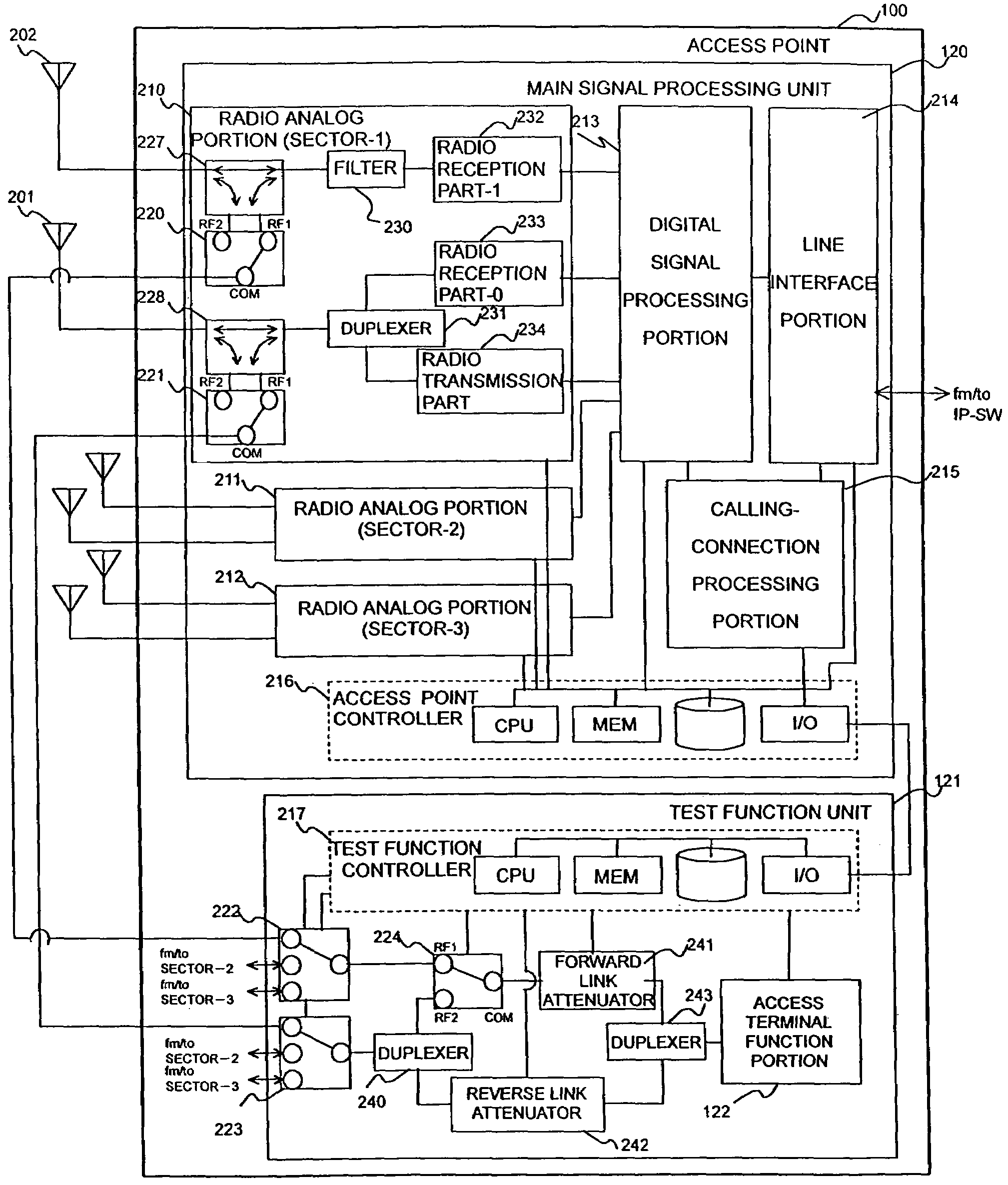
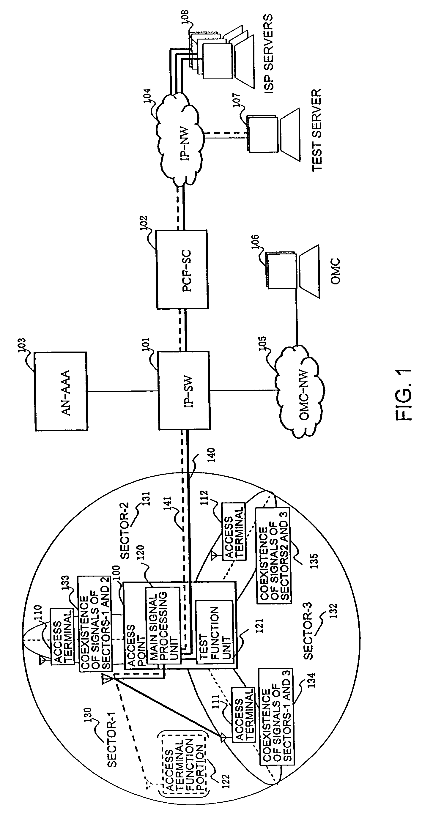
[0058]FIG. 1 is a configurational diagram of a radio access point testing system in a “1xEV-DO” system. The radio access point testing system includes an access point (radio access point testing apparatus) 100, an IP-SW (IP switch) 101, a PCF-SC (Packet Control Function-Session Control, radio packet control apparatus) 102, an AN-AAA (Access Network-Authentication, Authorization, and Accounting) 103, an OMC (Operation and Maintenance Center, maintenance apparatus) 106, a test server 107, and ISP (Internet Service Provider) servers 108.

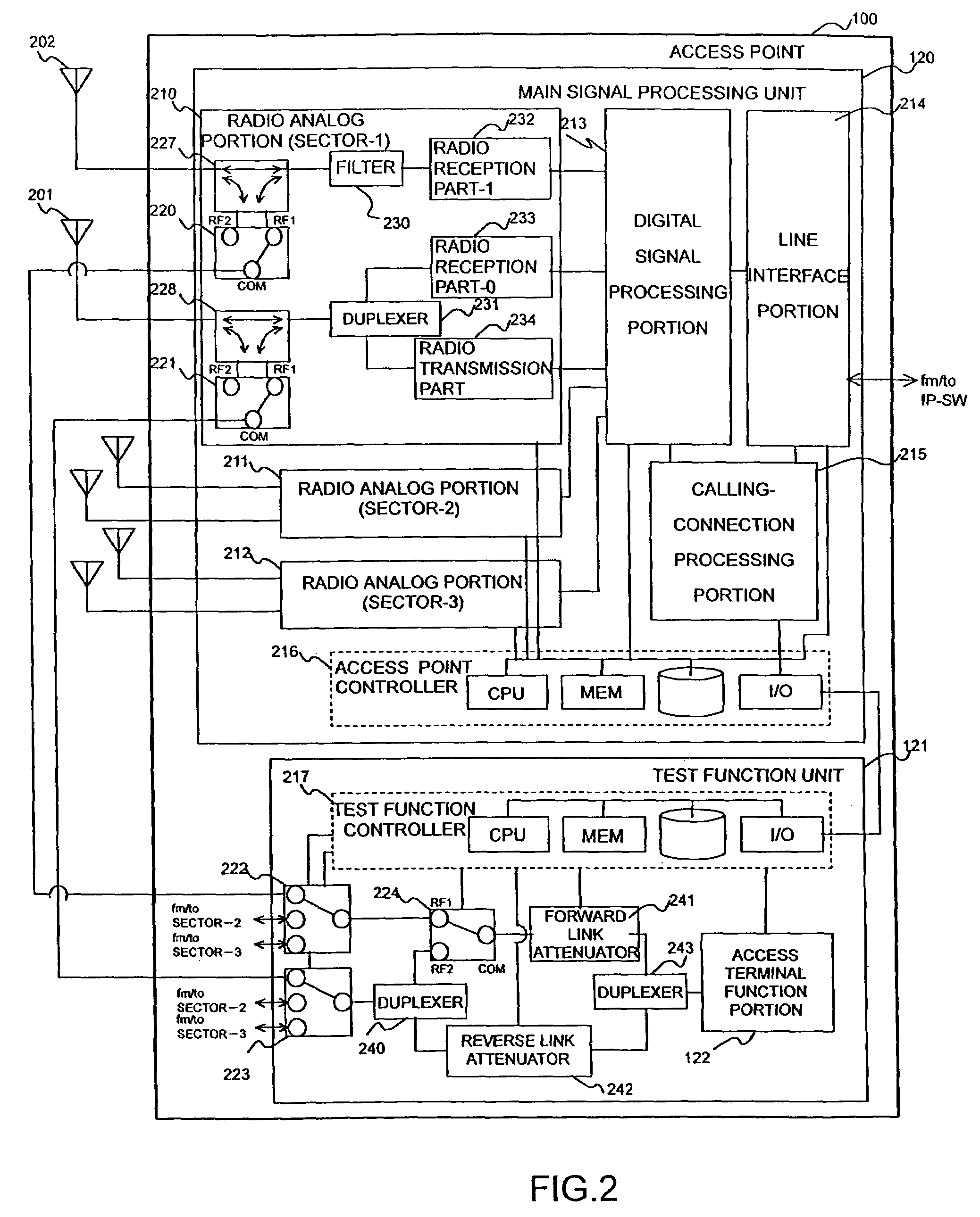
[0059]The access point 100 has a main signal processing unit 120, and a test function unit 121 including an access terminal function portion 122. This access point 1...


PUM


Abstract

The normality verification and radio characteristics test of a radio communication system are executed. RF-SWs (radio-frequency coaxial switches) change-over the paths of signals which are transmitted to and received from an access terminal function portion included in an access point. RF-SWs connect the access terminal function portion 122 with a desired one of radio analog portions. A test function controller controls the changeover operations of the RF-SWs in accordance with information designated by a maintenance apparatus (OMC). An access point controller controls in accordance with received test soil information, one or more of (1) an antenna failure test in which a voltage surface wave ratio is evaluated on the basis of the transmission power of the access terminal function portion, (2) a receiver failure test in which, after a packet error rate has been adjusted, a reception sensitivity is evaluated based on the transmission power of the access terminal function portion, and (3) a transmitter failure test in which transmission power from any of the radio analog portions is evaluated based on the reception power value of the access terminal function portion.

Description

BACKGROUND OF THE INVENTION[0001]The present invention relates to a radio access point testing method and testing apparatus, and more particularly to a radio access point testing method and testing apparatus which permit the radio characteristics test of a radio access point apparatus in a mobile communication system by remote manipulation from an operation center.[0002]Nowadays, mobile communication terminals have become smaller in size and lower in price with the miniaturizations of components, and the number of the users of the mobile communication terminals, such as portable telephones and personal handy system (PHS) telephones, have increased explosively. With the increase in the number of the users, enhancement in convenience has been more required of each system, and the enlargement of a service area and the rise of a data transmission rate have been furthered. The stability of the system is one of important factors for the convenience of the users. For the purpose of stably ...

Claims


Application Information

Patent Timeline
Patent Type & Authority Patents(United States)
IPC IPC(8): H04Q7/20H04M3/26H04B7/26H04B17/00H04B17/16H04B17/18H04B17/29H04W24/00H04W24/06
CPCH04W24/00H04W24/06
Inventor HASEGAWA, YOSHIAKIOOTA, SHINYAKANOMATA, YOSHIHIRONAKAGOSHI, ARATA
Owner HITACHI LTD
Learn More