Head stack assembly having an actuator body with multiple slots adjacent to a bore

Inactive Publication Date: 2008-05-06
WESTERN DIGITAL TECH INC
View PDF21 Cites 50 Cited by
  • Summary
  • Abstract
  • Description
  • Claims
  • Application Information

AI Technical Summary

Problems solved by technology

Some of the techniques require the use of an extra part in addition to the bearing assembly, such as a side screw, a tolerance ring or a C clip retainer ring, which adds to the cost of manufacturing disk drives.
Another technique for attaching the bearing assembly to the actuator body is the use of a press fit operation in which the bearing assembly is pressed into the bore thereby res

Method used


Image

  • Head stack assembly having an actuator body with multiple slots adjacent to a bore
  • Head stack assembly having an actuator body with multiple slots adjacent to a bore
  • Head stack assembly having an actuator body with multiple slots adjacent to a bore

Examples


Embodiment Construction

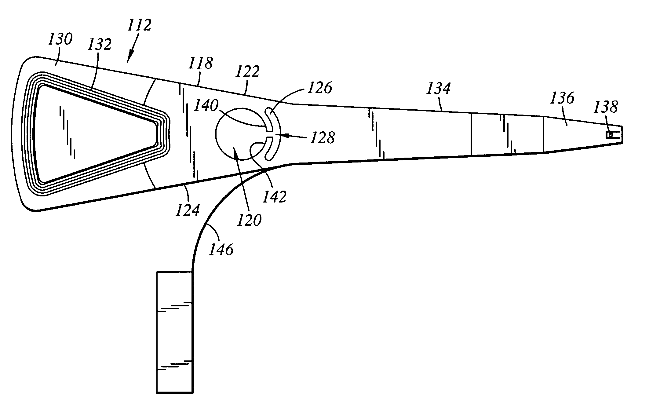
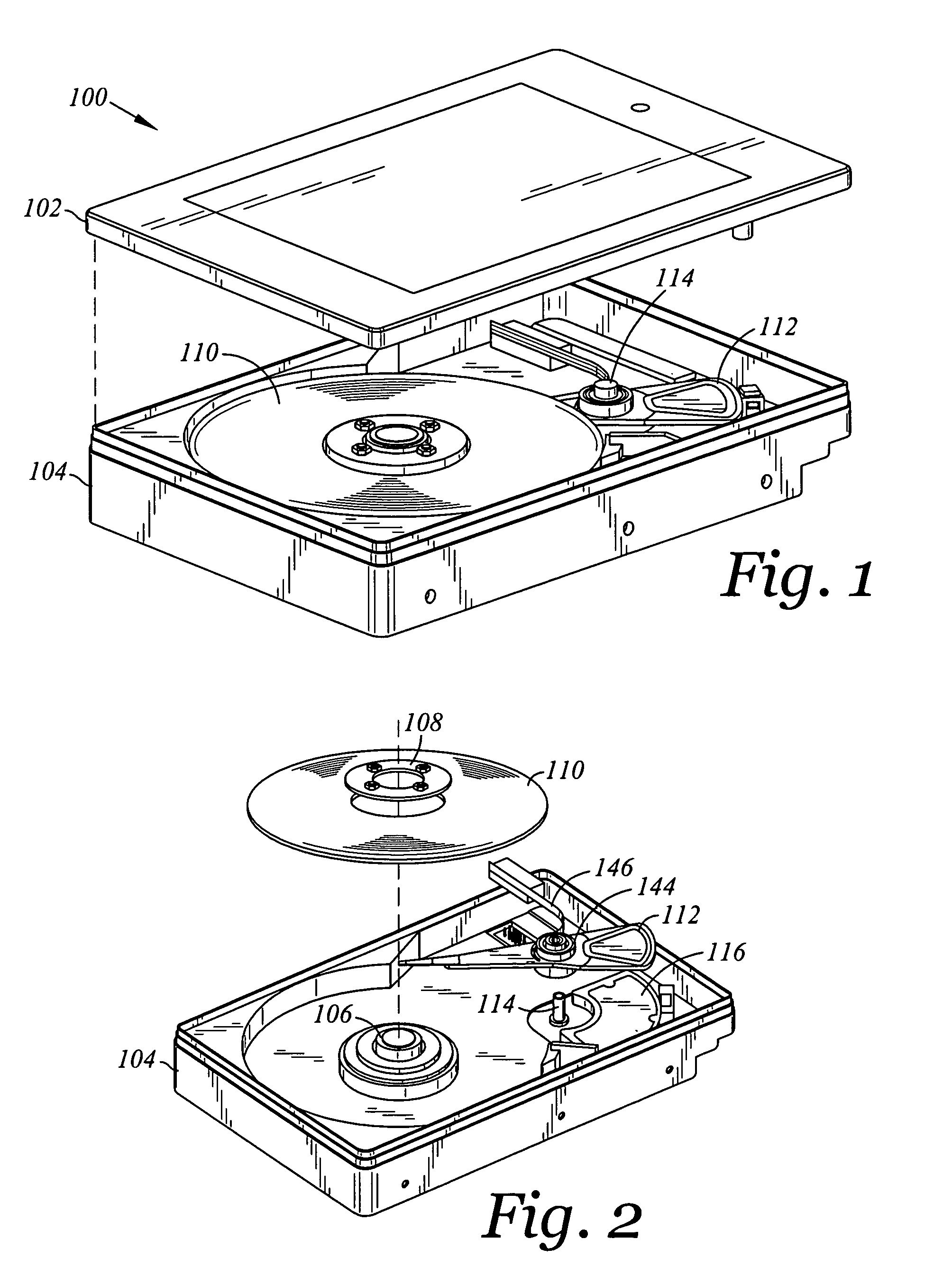
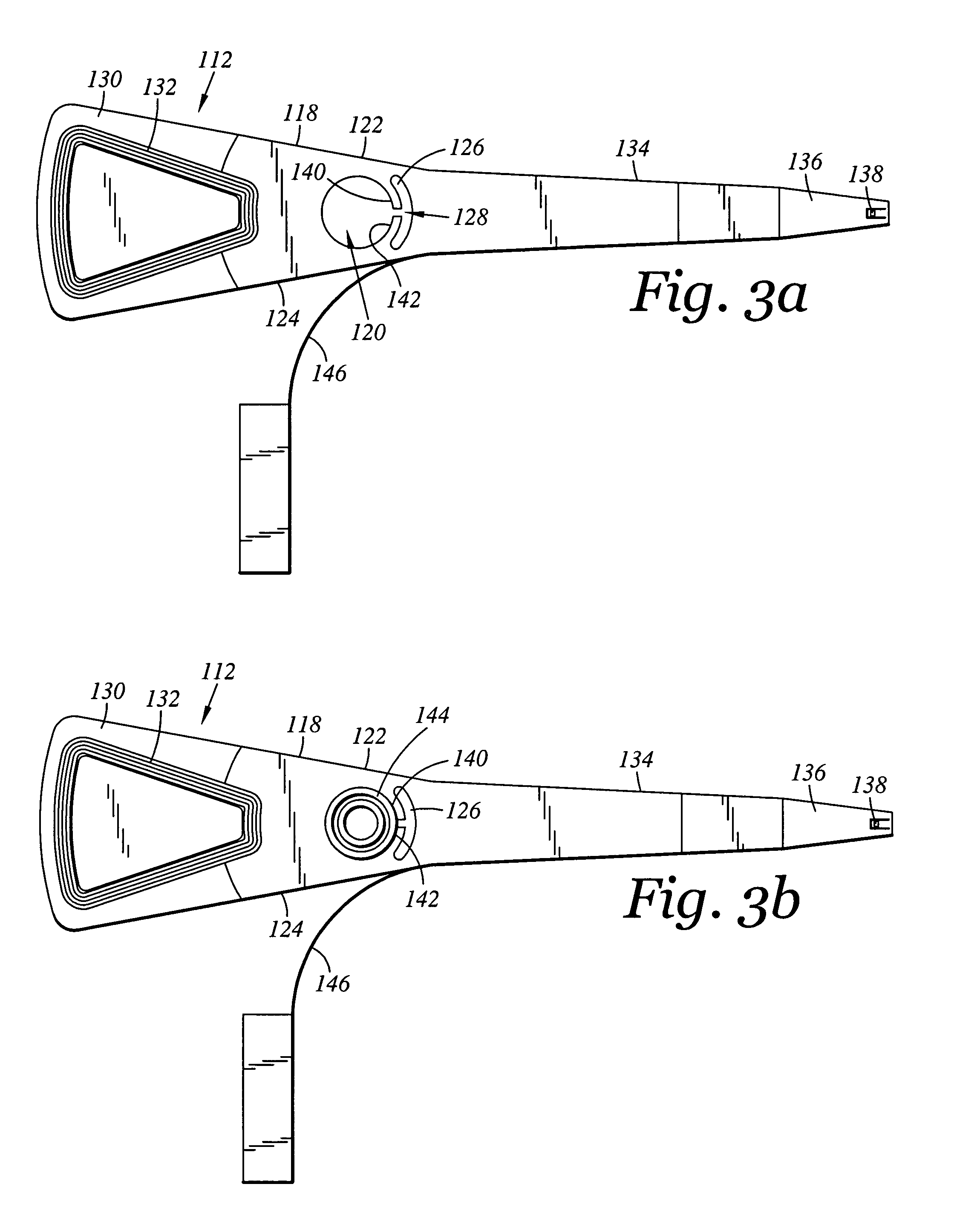
[0017]With reference to FIGS. 1, 2, 3a, and 3b, a disk drive 100 includes a base 104, a spindle motor 106 attached to base 104, a disk 110 positioned on spindle motor 106, and a head stack assembly 112 coupled to base 104. Head stack assembly 112 includes an actuator body 118. Actuator body 118 includes a pair of sides 122, 124, a bore 120 defining a longitudinal axis, a first slot 126 extending between pair of sides 122,124, a second slot 128 extending along a direction perpendicular to the longitudinal axis, second slot 128 extending from first slot 126 to bore 120. Head stack assembly 112 further includes a coil portion 130 cantilevered from actuator body 118 in one direction and an actuator arm 134 cantilevered from actuator body 118 in a direction opposite from coil portion 130.

[0018]Continuing with FIGS. 1 and 2, disk drive 100 further includes a cover 102 for attachment to base 104, a disk clamp 108 for clamping disk 110 to spindle motor 106, and a voice coil motor magnet ass...


PUM


Abstract

A head stack assembly for a disk drive includes an actuator body. The actuator body includes a pair of sides, a bore defining a longitudinal axis, a first slot extending between the pair of sides, a second slot extending along a direction perpendicular to the longitudinal axis, the second slot extending from the first slot to the bore. The head stack assembly further includes a coil portion cantilevered from the actuator body in one direction and an actuator arm cantilevered from the actuator body in a direction opposite from the coil portion.

Description

BACKGROUND OF THE INVENTION[0001]1. Field of the Invention[0002]This invention relates to a head stack assembly used in a disk drive. More particularly, this invention relates to a head stack assembly having an actuator body with multiple slots adjacent to its bore.[0003]2. Description of the Prior Art and Related Information[0004]A huge market exists for disk drives such as hard disk drives for mass-market host computer systems such as servers, desktop computers, and laptop computers. To be competitive in this market, a hard disk drive must be relatively inexpensive, and must accordingly embody a design that is adapted for low-cost mass production. In addition, it must provide substantial capacity, rapid access to data, and reliable performance. Numerous manufacturers compete in this huge market and collectively conduct substantial research and development, at great annual cost, to design and develop innovative hard disk drives to meet increasingly demanding customer requirements.[...

Claims


Application Information

Patent Timeline
IPC IPC(8): G11B21/08
CPCG11B5/4813
Inventor MOHAJERANI, KHOSROW
Owner WESTERN DIGITAL TECH INC
Why Eureka
Try Eureka