X-ray diagnostics device and method for controlling an X-ray diagnostics device

a diagnostic device and x-ray technology, applied in diagnostics, medical science, electrical equipment, etc., can solve the problems of blurred details, low signal-to-noise ratio of objects, and inability to adjust pulse durations optimally in terms of avoiding motion blurs, so as to ensure the maximum recognizability of moved details

Inactive Publication Date: 2008-05-13
SIEMENS AG
View PDF9 Cites 27 Cited by
  • Summary
  • Abstract
  • Description
  • Claims
  • Application Information

AI Technical Summary

Benefits of technology

[0009]The object is achieved according to the invention for an x-ray diagnostics device such that a computing unit is assigned to the control device, said computing unit determining the spatial frequency-dependent signal-to-noise ratio (S / N) on the basis of the parameter and calculating therefrom the duration of the x-ray pulse and / or the remaining parameters necessary for a recording. This allows moved objects to be optimally recognized.
[0010]It has proven advantageous to provide a storage device in which characteristics of the objects to be recorded, such as the motion speed for instance, are stored.
[0015]According to the invention, the object is achieved for a method in that the duration of the x-ray pulse is controlled such that the recognizability of relevant moved objects is maximal.

Problems solved by technology

A dilemma arises with the search for imaging parameters which result in the best possible recognizability of moved details with a weak image contrast.
Although short x-ray pulses result in a slight motion blur in the image, they only deliver a low dose so that the signal-to-noise ratio of the object is low.
Longer x-ray pulses allow a higher signal-to-noise ratio, but nevertheless result in blurred details.
In this case, the adjustment of the tube voltage, the tube current, the filter used and the imaging geometry have a significant influence on the dose so that the pulse duration adjusted by the AEC is not optimal in terms of avoiding motion blurs.
The movement of the objects to be examined is however not taken into consideration, thereby rendering a minimization of blur artifacts impossible.

Method used


Image

  • X-ray diagnostics device and method for controlling an X-ray diagnostics device
  • X-ray diagnostics device and method for controlling an X-ray diagnostics device

Examples


Embodiment Construction

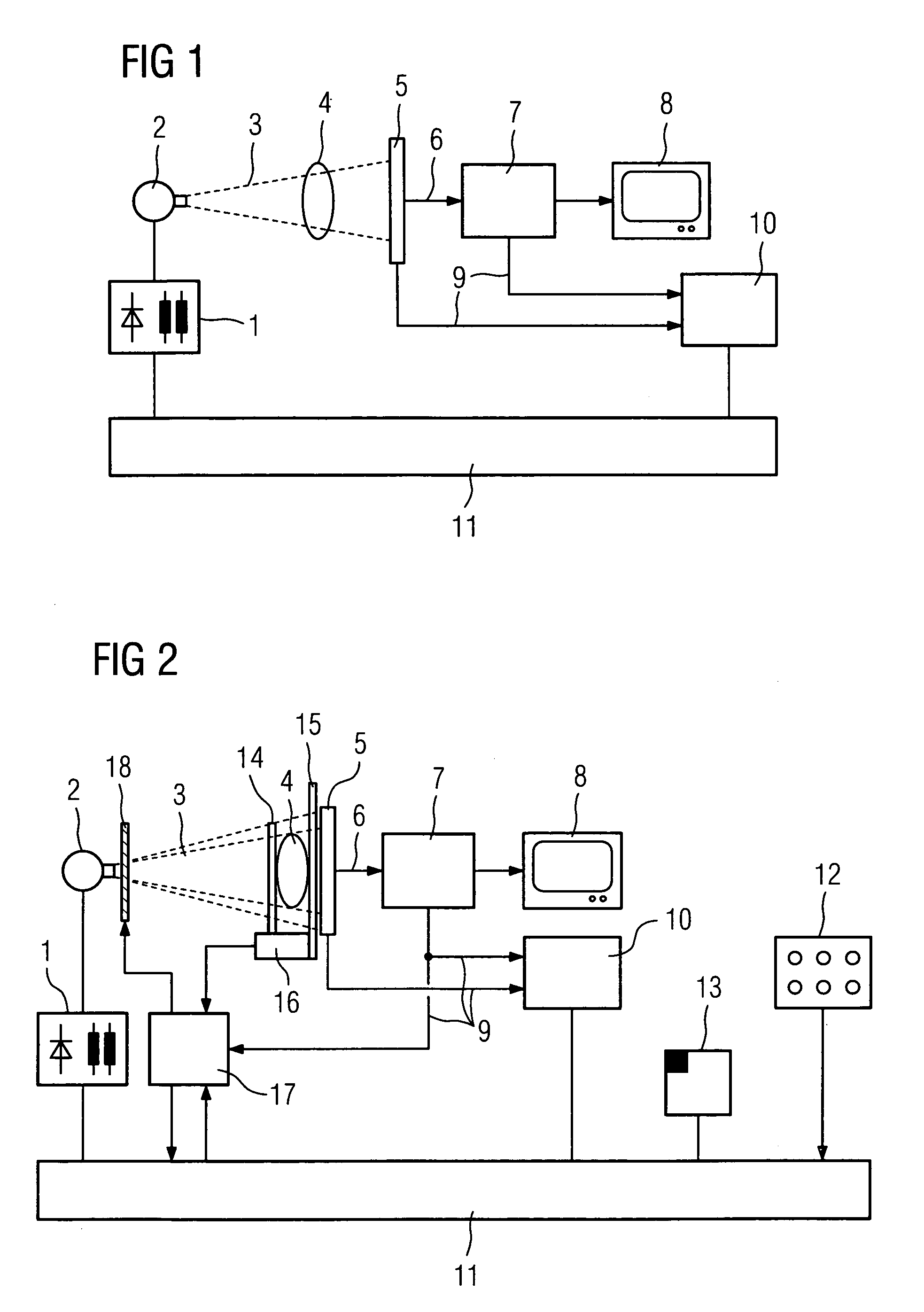
[0022]The x-ray diagnostics device 1 to 11 shown in FIG. 2 basically operates as described in FIG. 1. The doctor now enters the desired direction of projection, the distance between x-ray emitter and detector (SID), the organ program etc, via a control panel 12. If the selected organ is known, the typically occurring speeds of the relevant details are also known, which can be stored for instance in a storage device 13.

[0023]Since it is desirable for the calculation described further below to know the thickness of the patient, this is determined as far as possible according to one of the following methods. The thickness can be measured for instance on a measuring system 16 with the aid of two limitations 14 and 15, with these limitations possibly being of a mechanical nature, but also being able to be implemented by light sensors, electromagnetic sensors or in another manner. However, the thickness can also be estimated computationally in a known manner from the so-called water equiv...


PUM


Abstract

The invention relates to an x-ray diagnostics device having an x-ray tube for generating x-rays operated by a high voltage generator, having an x-ray detector for converting incident x-rays into electrical signals, having an image processing system and a control device for the duration of the x-ray pulse, in which parameters of the x-ray diagnostics device can be adjusted, with a computing unit being assigned to the control device, said computing unit determining the spatial frequency-dependent signal-to-noise ratio on the basis of the parameters and calculating therefrom the duration of the x-ray pulse and / or the remaining parameters required for a recording. The invention further relates to a method of this type for controlling the x-ray diagnostics device, in which the duration of the x-ray pulse is controlled such that the recognizability of relevant, moved objects is maximal.

Description

CROSS REFERENCE TO RELATED APPLICATIONS[0001]This application claims priority to the German Application No. 10 2005 006 895.2, filed Feb. 15, 2005 which is incorporated by reference herein in its entirety.FIELD OF INVENTION[0002]The invention relates to an x-ray diagnostics device having an x-ray tube for generating x-rays operated by a high voltage generator, having an x-ray detector for converting incident x-rays into electrical signals, having an image processing system and a control device for the duration of the x-ray pulse, in which the parameters of the x-ray diagnostics device can be adjusted, and to a method for controlling an x-ray diagnostics device of this type.BACKGROUND OF INVENTION[0003]X-ray systems are generally used in pulsed operation, i.e. the x-ray tube emits an x-ray pulse of a specific duration per image to be recorded. This is particularly advantageous for the display of moved objects. There is thus usually a risk that details of the human body are reproduced...

Claims


Application Information

Patent Timeline
Patent Type & Authority Patents(United States)
IPC IPC(8): H05G1/22
CPCA61B6/542A61B6/545A61B6/503
Inventor BERNHARDT, PHILIPPHOHEISEL, MARTIN
Owner SIEMENS AG
Why Eureka
Try Eureka