Safety gate assembly

a gate and safety technology, applied in the direction of door/window fittings, fastening means, building components, etc., can solve the problems of gate moving through the fully closed position and failing to latch

Inactive Publication Date: 2008-05-20
BETTACARE
View PDF6 Cites 40 Cited by
  • Summary
  • Abstract
  • Description
  • Claims
  • Application Information

AI Technical Summary

Benefits of technology

[0008]According to the present invention, in a safety gate assembly of the type referred to above, the latch member cooperates with biasing means arranged to move the latch member in the direction away from the said one side of the gate and the latch defines a recess, which is adapted to accommodate a portion of the latch member and laterally adjacent which is an entry ramp and extending vertically into which is an exit ramp, the entry ramp being constructed and arranged so that when the gate is pivoted into the closed position the latch member engages the entry ramp and is moved by it progressively against the force of the biasing means in the direction towards the said one side of the gate until the latch member is in registry with the recess and the biasing means then urges the latch member into the recess and further pivotal movement of the gate is prevented and the gate is in the locked position, the exit ramp being constructed and arranged so that when the gate is moved linearly upwardly the latch member engages the exit ramp and is moved by it progressively in the direction towards the said one side of the gate until it is out of the recess, whereafter the gate may be moved pivotally into the open position.
[0009]The gate in accordance with the invention is thus similar to that disclosed in WO 02 / 48496 in that it can move vertically between two positions and is latched in one of them and unlatched in the other. However, the gate in accordance with the prior documents is normally in the higher position and only enters the lower position when it is latched. The gate in accordance with the present invention, on the other hand, is normally in the lower position and is latched in the lower position and is only moved into the higher position to unlatch it. The construction of the latch is also very different to that in the prior document because the gate includes a latch member which is biased outwardly, that is to say away from the hinge connections, and the latch includes an entry ramp which is engaged by the latch member as the gate is closed and progressively forces the latch member inwardly, that is to say towards the hinge connections, against the biasing force acting on it. As the gate continues to move, the latch member move into alignment with the recess in the latch and the biasing means then moves the latch member outwardly, that is to say into the recess. The gate is then latched. Communicating with the recess is an exit ramp which extends upwardly and towards the hinge connections. If the gate is moved bodily upwardly, the latch member slides along the exit ramp and is progressively moved towards the hinge connections until it is outside the recess, whereafter the gate may be opened. This method of latching and unlatching is simpler than that in the prior document and the different configuration and manner of use of the latch means that there is no danger of the support member, if present, being damaged. Furthermore, the risk present in the gate assembly of the prior document of failing to latch is eliminated.
[0016]It is preferred that the support member is removably connected to the frame and defines two helical ramps which are oppositely inclined, the support member being selectively connected to the frame such that a selected one of the two helical ramps is upwardly directed and supports the gate. Thus if the orientation of the latch member is reversed, as described above, to convert the gate from one which opens eg clockwise to one which opens anti-clockwise, it is necessary to ensure that the self-closing force acting on the gate also acts in the opposite direction and this may be achieved simply and effectively by the provision of this feature which enable the support member to be simply disconnected from the frame and then reconnected in the opposite orientation so that the other helical ramp, which descends in the opposite sense, is upwardly directed and supports the weight of the gate.

Problems solved by technology

If this were the case and if the gate were slammed very violently, it would be possible for the gate to be moving so rapidly that the biasing means would be unable to react sufficiently rapidly to force the latch member into the recess and this would result in the gate moving through the fully closed position and failing to latch.

Method used


Image

  • Safety gate assembly
  • Safety gate assembly
  • Safety gate assembly

Examples


Embodiment Construction

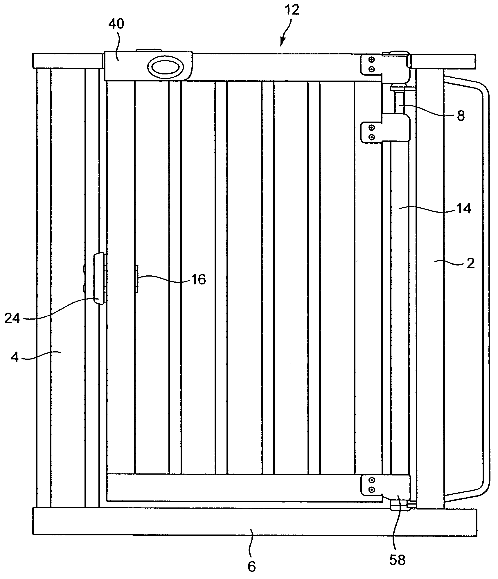
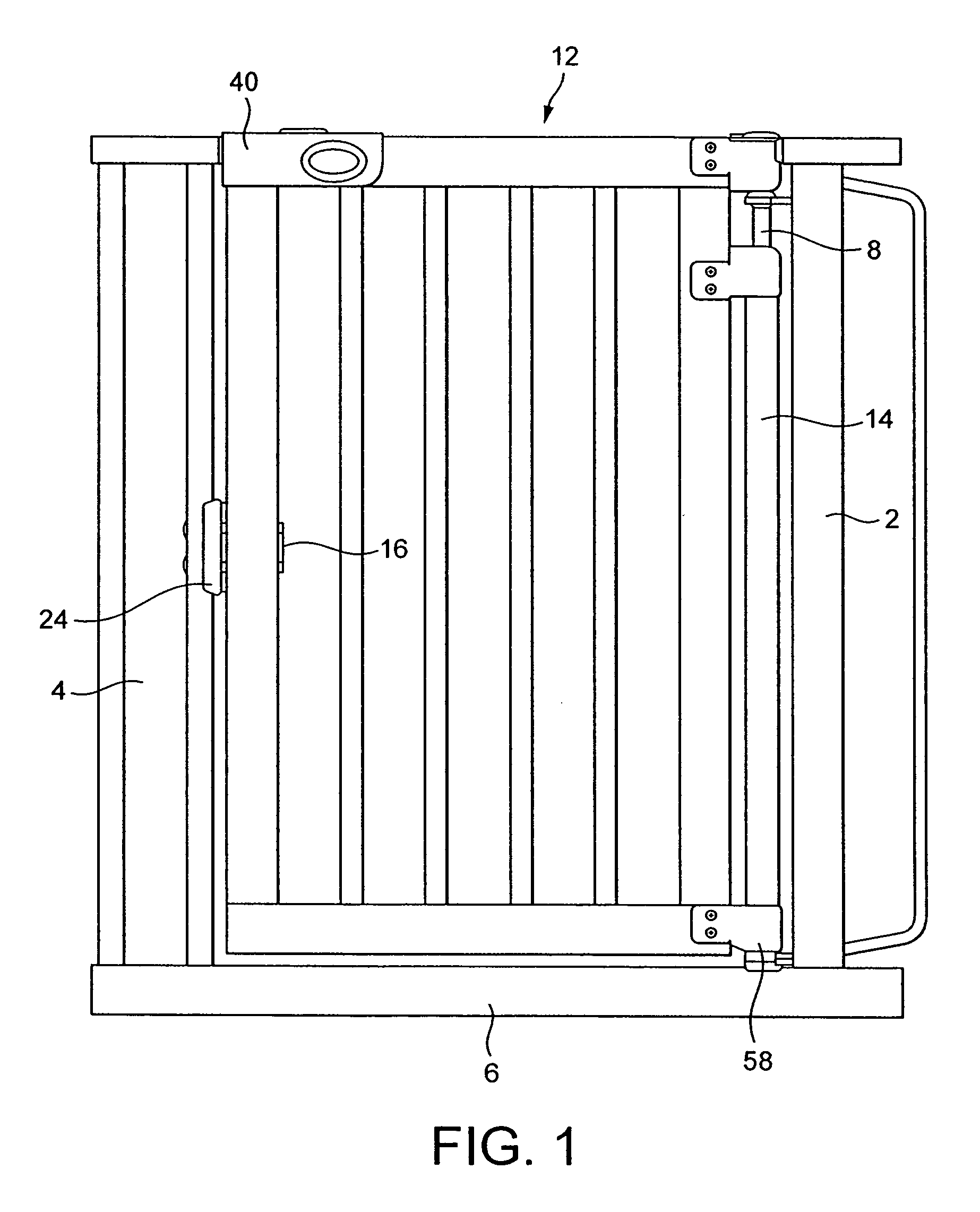
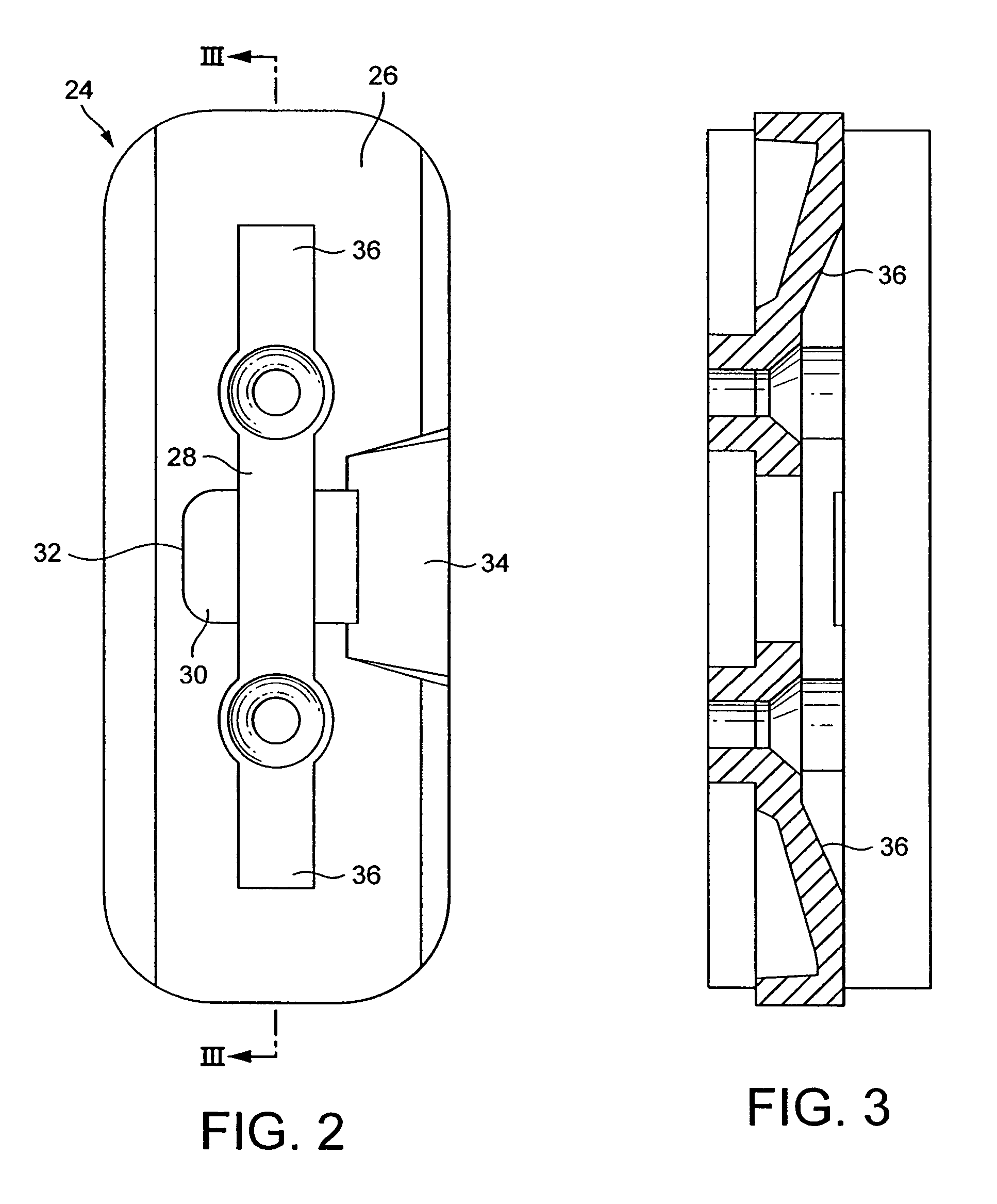
[0026]The gate assembly comprises a generally U-shaped frame comprising two vertically extending limbs 2, 4, the lower ends of which are connected by a horizontal base 6. In use, the frame is secured in position in a doorway, passage or stairway by any conventional means, such as screw threaded rods, which are received in holes at the top and bottom of each limb 2, 4 and carry clamping members at their free ends (not shown). At its upper end, the limb 2 carries a downwardly extending hinge pin 8 and at the end of the base 6 adjacent the limb 2, the base carries an upwardly extending hinge pin 10 (seen in FIG. 6). Pivotally mounted within the opening defined by the frame is a gate 12. On its side adjacent the limb 2, the gate carried a hollow, open-ended hinge tube 14 in which the hinge pins 8 and 10 are rotatably and longitudinally slidably received. The tube 14 and hinge pins 8 and 10 constitute the pivotal connection between the frame and the gate.

[0027]As best seen in FIG. 4, on ...


PUM


Abstract

A safety gate assembly includes a frame which may be secured across a door opening, stairway or the like and comprises a base and two upstanding limbs and a gate. One side of the gate is connected by one or more pivotal connections to the one limb of the frame to permit pivotable movement of the gate with respect to the frame about a pivotal axis. The other side of the gate carries a latch member, which cooperates with a latch connected to the other limb of the frame. The latch defines a locked position, in which pivotable movement of the gate is prevented. The pivotal connection is constructed to permit linear movement of the gate relative to the frame in a direction parallel to the pivotal axis. The latch member cooperates with a biasing spring arranged to urge the latch member in the direction away from the said one side of the gate. The latch defines a recess, which is adapted to accommodate a portion of the latch member and laterally adjacent which is an entry ramp and extending vertically into which is an exit ramp. The entry ramp is constructed and arranged so that when the gate is pivoted into the closed position the latch member engages the entry ramp and is moved progressively against the force of the biasing means in the direction towards the said one side of the gate until the latch member is in registry with the recess and the biasing means then urges the latch member into the recess. Further pivotal movement of the gate is then prevented and the gate is in a locked position. The exit ramp is constructed and arranged so that when the gate is moved linearly upwardly, the latch member engages the exit ramp and is moved by it progressively in the direction towards the said one side of the gate until it is out of the recess, whereafter the gate may be moved pivotally into the open position.

Description

FIELD OF THE INVENTION[0001]The present invention relates to a childproof safety gate assembly, particularly of self-closing and self-latching type, which can be fitted across a doorway, stairway, or the like. A childproof safety gate is one which may be readily opened by an adult but which a small child is incapable of opening. More specifically, the present invention relates to a safety gate assembly of the type including a frame which may be secured across a door opening, stairway or the like, the frame comprising a base and at least one upstanding limb, and a gate, one side of which is connected by one or more pivotal connections to the one limb of the frame to permit pivotal movement of the gate with respect to the frame about a pivotal axis and the other side of which carries a projecting latch member, which cooperates with a latch connected to the other side of the frame, the latch defining a locked position, in which pivotal movement of the gate is prevented, the pivotal con...

Claims


Application Information

Patent Timeline
Patent Type & Authority Patents(United States)
IPC IPC(8): E06B3/68E05F1/06E06B9/04
CPCE05F1/066E06B9/04E05Y2800/426E05Y2900/40E06B2009/002Y10T292/11
Inventor JEFFERYS, PATRICK CRAWFORDNEWCOMBE, VAUGHAN STEPHEN
Owner BETTACARE
Why Eureka
Try Eureka