Inverting vacuum panels for a plastic container

a vacuum panel and plastic container technology, applied in the field of side panels of plastic containers, can solve the problems of spherulitic morphology, the container cannot withstand temperature and time demands, and the non-high acid content commodities are not generally acceptable, so as to achieve the effect of decreasing the volume of the container

Inactive Publication Date: 2008-05-27
AMCOR RIGID PLASICS USA LLC
View PDF35 Cites 36 Cited by
  • Summary
  • Abstract
  • Description
  • Claims
  • Application Information

AI Technical Summary

Benefits of technology

[0016]Accordingly, this invention provides for inverting vacuum panels for a plastic container which maintain aesthetic and mechanical integrity during any subsequent handling after being hot-filled and cooled to ambient having a structure that is designed to distort inwardly in a controlled manner so as to allow for significant absorption of vacuum pressures without unwanted deformation.
[0017]The present invention includes a sidewall portion of a plastic container, the container having an upper portion, the sidewall portion, and a base. The upper portion includes an opening defining a mouth of the container. The sidewall portion extends from the upper portion to the base. The sidewall portion includes generally rectangular shaped vacuum panels defined in at least part by an upper portion, a central portion, and a lower portion each having an underlying surface with a series of equidistantly spaced indents formed therein. At least the central portion underlying surface having a generally convex shape in cross section. The vacuum panels being moveable to accommodate vacuum forces generated within the container thereby decreasing the volume of the container.

Problems solved by technology

The hot filling process is acceptable for commodities having a high acid content, but not generally acceptable for non-high acid content commodities.
Pasteurization and retort both present an enormous challenge for manufactures of PET containers in that heat-set containers cannot withstand the temperature and time demands required of pasteurization and retort.
On amorphous material, thermal processing of PET material results in a spherulitic morphology that interferes with the transmission of light.
In other words, the resulting crystalline material is opaque, and thus, generally undesirable.
This product shrinkage phenomenon results in the creation of a vacuum within the container.
If not controlled or otherwise accommodated, these vacuum pressures result in deformation of the container, which leads to either an aesthetically unacceptable container or one that is unstable.
One drawback with the use of nitrogen dosing technology however is that the maximum line speeds achievable with the current technology is limited to roughly 200 containers per minute.
Such slower line speeds are seldom acceptable.
Additionally, the dosing consistency is not yet at a technological level to achieve efficient operations.
Minimizing headspace requires more precession during filling, again resulting in slower line speeds.
Reducing fill temperature is equally disadvantageous as it limits the type of commodity suitable for the container.
Traditionally, these paneled areas have been semi-rigid by design, unable to accommodate the high levels of vacuum pressures currently generated, particularly in lightweight containers.

Method used


Image

  • Inverting vacuum panels for a plastic container
  • Inverting vacuum panels for a plastic container
  • Inverting vacuum panels for a plastic container

Examples


Embodiment Construction

[0042]The following description of the preferred embodiments is merely exemplary in nature, and is in no way intended to limit the invention or its application or uses.

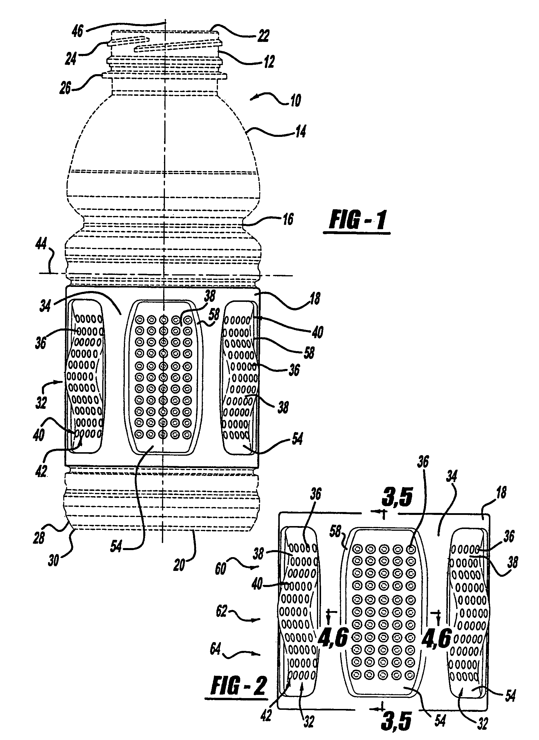
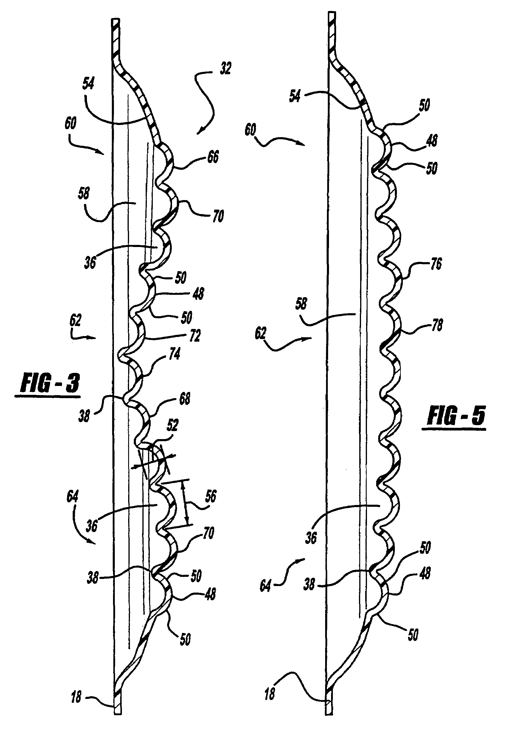
[0043]As discussed above, to accommodate vacuum forces during cooling of the contents within a heat-set container, containers generally have a series of vacuum panels around their sidewall. Traditionally, these vacuum panels have been semi-rigid and incapable of preventing unwanted distortion elsewhere in the container, particularly in lightweight containers.

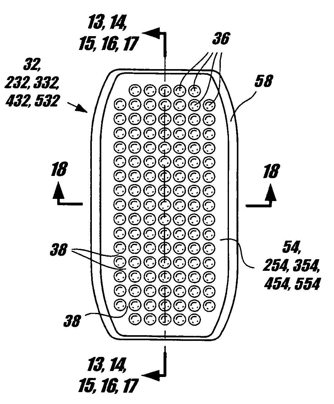
[0044]Referring now to the drawings, there is depicted a sidewall portion of a plastic container embodying the concepts of the present invention. The drawings show the sidewall portion of the present invention, generally identified by reference numeral 18, adapted to cooperate with a specific plastic container 10. However, the teachings of the present invention are more broadly applicable to sidewall portions for a large range of plastic containers.

[0045]Before ad...


PUM


Abstract

A sidewall portion of a plastic container adapted for vacuum pressure absorption. The sidewall portion including generally rectangular shaped vacuum panels equidistantly spaced about the container. The vacuum panels having, at least in part, a convex shaped surface and a series of equidistantly spaced indents disposed therein. The vacuum panels being moveable to accommodate vacuum forces generated within the container thereby decreasing the volume of the container.

Description

CROSS-REFERENCE TO RELATED APPLICATION[0001]This application is a continuation-in-part of U.S. Ser. No. 10 / 361,356, filed Feb. 10, 2003, U.S. Pat. No. 6,920,992 issued on Jul. 26, 2005 and commonly assigned.TECHNICAL FIELD OF THE INVENTION[0002]This invention generally relates to side panels for plastic containers that retain a commodity, and in particular a liquid commodity. More specifically, this invention relates to inverting vacuum panels formed in a plastic container that allow for significant absorption of vacuum pressures without unwanted deformation in other portions of the container.BACKGROUND OF THE INVENTION[0003]As a result of environmental and other concerns, plastic containers, more specifically polyester and even more specifically polyethylene terephthalate (PET) containers, are now being used more than ever to package numerous commodities previously packaged in glass containers. Manufacturers and fillers, as well as consumers, have recognized that PET containers are...

Claims


Application Information

Patent Timeline
Patent Type & Authority Patents(United States)
IPC IPC(8): B65D1/02B65D1/46B65D79/00
CPCB65D1/0223B65D1/42B65D79/005B65D79/0084
Inventor LANE, MICHAEL T.STEIH, RICHARD J.GAMBER, DANIEL W.BROWN, RANDALL S.JOSHI, ROHIT V.
Owner AMCOR RIGID PLASICS USA LLC
Why Eureka
Try Eureka