Light source device and crystal display device
a technology of liquid crystal display and light source, which is applied in the direction of lighting and heating apparatus, polarising elements, instruments, etc., can solve the problems of high manufacturing cost, easy scratching of prism sheets, waste of balance as absorption loss, and high manufacturing cost, so as to achieve high efficiency, increase light utilization efficiency, and low cost
- Summary
- Abstract
- Description
- Claims
- Application Information
AI Technical Summary
Benefits of technology
Problems solved by technology
Method used
Image
Examples
example 1
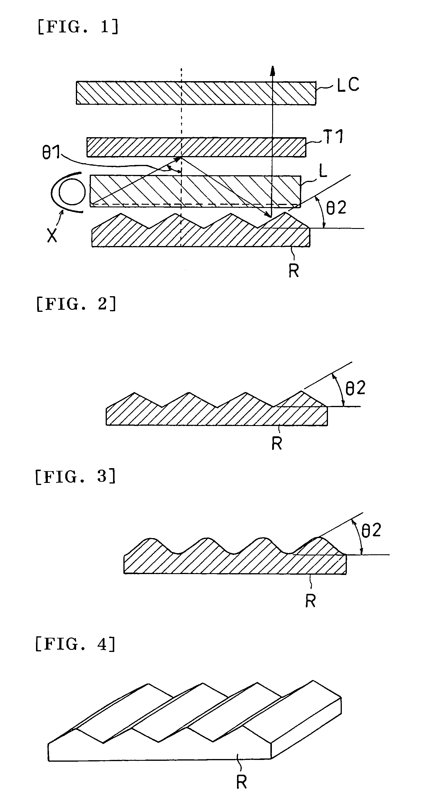
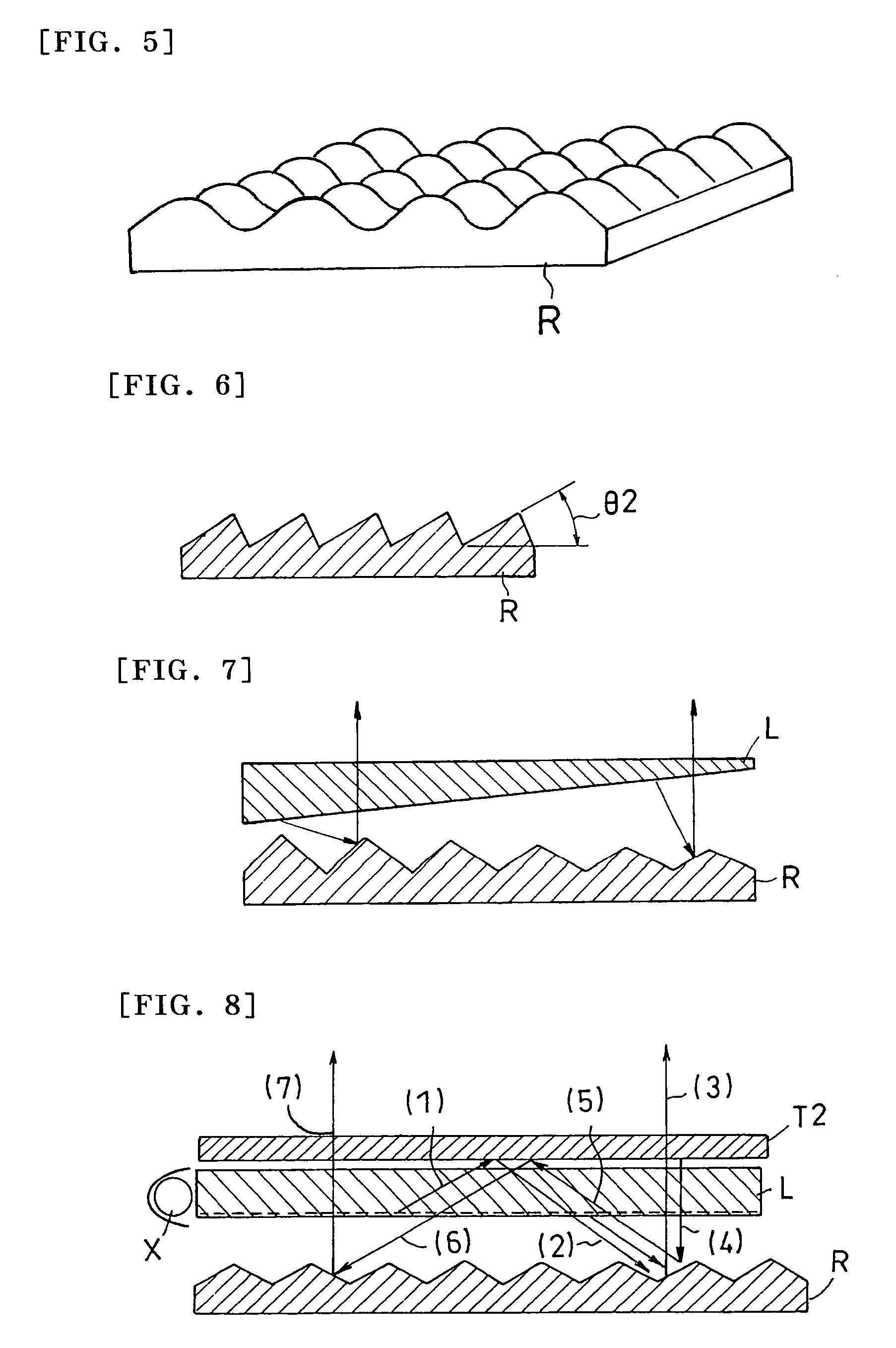
[0315]Used as a light guide plate (L) was a wedge type sidelight light guide plate taken out of a 15 in TFT liquid crystal panel manufactured by International Business Machines Corporation. A peak angle (θ1) in an emitting light direction was about 80°.
[0316]Used as a reflection plate (R) was a silver vapor deposited reflection plate with surface depressions and protrusions, which were formed by transferring a surface profile of a brass mold fabricated by using an epoxy-based UV curable resin (KR400) manufactured by ASAHI DENKA KOGYO Co., Ltd. and cutting a precursor of the mold on a PET substrate with a 100 μm pitch (Lumirror T600, manufactured by TORAY INDUSTRIES, INC.). Silver vapor deposition was conducted on the surface profile to thereby obtain the silver vapor-deposited reflection plate with depressions and protrusions on a surface thereof. A surface of the silver vapor-deposited reflection plate was smooth and of a line type of symmetrical structure (corresponding to FIG. 4)...
example 2
[0324]Used as a light guide plate (L) was a wedge type sidelight light guide plate taken out of a 15.1 inch LCD housing manufactured by Hitachi Ltd. A peak angle (θ1) in the emitting light direction was about 70°.
[0325]A reflection plate (R) was, in a first step, fabricated as a surface profile plate shown in FIG. 3 by emboss rolling a surface of a hard vinyl chloride plate (with a thickness of 1 mm) manufactured by Mitsubishi Plastic, Inc. The plate had a pitch of about 100 μm in raised portions. Aluminum was vacuum vapor deposited on the obtained surface profile to a thickness of 0.1 μm to thereby obtain a reflection plate with depressions and protrusions thereon. An average slope angle (θ2) of depressions and protrusions on the surface (repetitive slope structure) was about 35°.
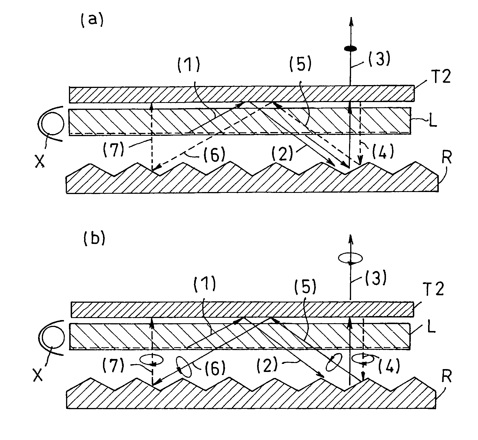
[0326]Used as a transmittance angle dependent polarizing layer (T2) was a polarizing element (A) with a structure in which a retardation plate (b1) was inserted between linear polarization type reflection ...
example 3
[0332]Used as a light guide plate (L) was a two lamp type sidelight light guide plate taken out of a light box (Light Pure-7000pro) manufactured by HakubaPhoto Industry Co., Ltd. A peak angle (θ1) in the emitting light direction was about 70°.
[0333]A reflection plate (R) was obtained as a reflection plate with a surface structure, which corresponds to that shown in FIG. 4 fabricated in a procedure in which a silver vapor deposited PET film (BL film, manufactured by Oike Industrial Co., Ltd., with a thickness of 50 μm) was folded at points with a pitch of 5 mm and the folded film was adhered on a cut aluminum substrate with a ridge repetitive surface structure each of which has a predetermined angle. An average slope angle (θ2) of the surface structure (a repetitive slope structure) was about 35°. The reflection plate exposes the PET substrate layer of the silver vapor deposited PET film on the front side, while adhering to the aluminum substrate by the vapor deposited surface, and t...
PUM
| Property | Measurement | Unit |
|---|---|---|
| angle | aaaaa | aaaaa |
| angle | aaaaa | aaaaa |
| angle | aaaaa | aaaaa |
Abstract
Description
Claims
Application Information
 - R&D
- Intellectual Property
- Life Sciences
- Materials
- Tech Scout
- Unparalleled Data Quality
- Higher Quality Content
- 60% Fewer Hallucinations
Browse by: Latest US Patents, China's latest patents, Technical Efficacy Thesaurus, Application Domain, Technology Topic, Popular Technical Reports.
© 2025 PatSnap. All rights reserved.Legal|Privacy policy|Modern Slavery Act Transparency Statement|Sitemap|About US| Contact US: help@patsnap.com


