Light source device and crystal display device

a technology of liquid crystal display and light source, which is applied in the direction of lighting and heating apparatus, polarising elements, instruments, etc., can solve the problems of high manufacturing cost, easy scratching of prism sheets, waste of balance as absorption loss, and high manufacturing cost, so as to achieve high efficiency, increase light utilization efficiency, and low cost

Inactive Publication Date: 2007-01-18
NITTO DENKO CORP
View PDF13 Cites 46 Cited by
  • Summary
  • Abstract
  • Description
  • Claims
  • Application Information

AI Technical Summary

Benefits of technology

[0077] In FIG. 10(a), there is shown a case where the optical layer (D) having a polarization canceling ability is disposed between the transmittance angle dependent polarizing layer (T2) and the sidelight type backlight light guide plate (L). In FIG. 10(b), there is shown a case where the optical layer (D) having a polarization canceling ability is disposed between the sidelight type backlight light guide plate (L) and the reflection plate (R). In FIG. 10(c), there is shown an example case where the optical layer (D) having a polarization canc...

Problems solved by technology

A manufacturing cost has been, in more of cases, high because of its structure.
A combination of a light guide plate and a prism sheet generally available in the market renders the prism sheet easily scratched and problematic in handling since the prism sheet is disposed on the upper surface side of the light guide plate.
A liquid display using a reflection polarizer as a light source, which has been generally used, can be theoretically expected to have two hold brightness, but an actual brightness is limited to a value on the order of 1.5-hold and the balance is wasted ...

Method used


Image

  • Light source device and crystal display device
  • Light source device and crystal display device
  • Light source device and crystal display device

Examples


example 1

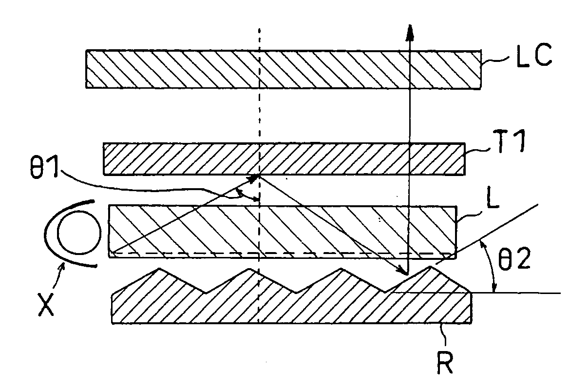
[0314] Used as a light guide plate(L) was a wedge type sidelight light guide plate taken out of a 15 in TFT liquid crystal panel manufactured by International Business Machines Corporation. A peak angle (θ1) in an emitting light direction was about 80°.

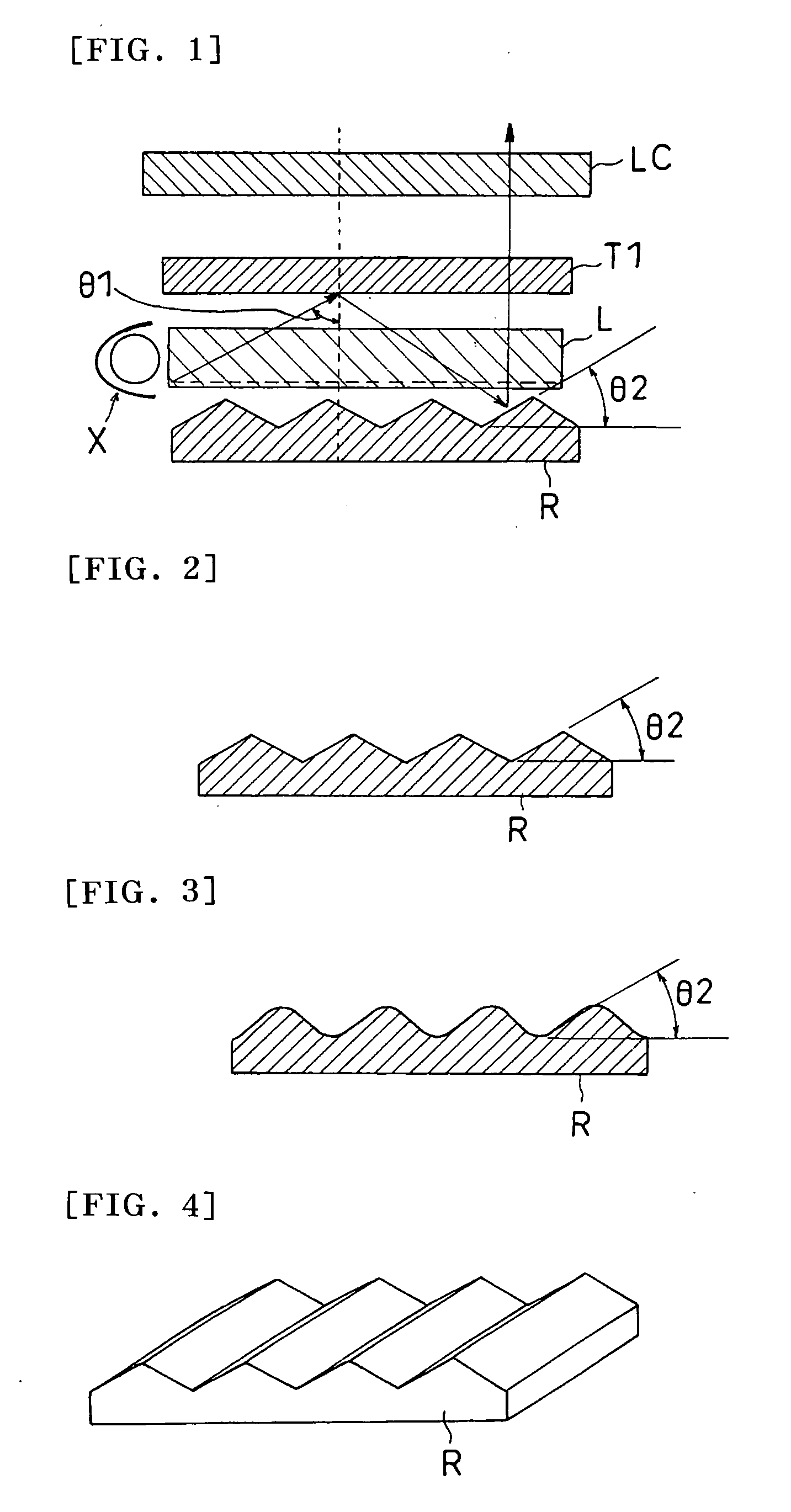
[0315] Used as a reflection plate(R) was a silver vapor deposited reflection plate with surface depressions and protrusions, which were formed by transferring a surface profile of a brass mold fabricated by using an epoxy-based UV curable resin (KR400) manufactured by ASAHI DENKA KOGYO Co., Ltd. and cutting a precursor of the mold on a PET substrate with a 100 μm pitch (Lumirror T600, manufactured by TORAY INDUSTRIES, INC.). Silver vapor deposition was conducted on the surface profile to thereby obtain the silver vapor-deposited reflection plate with depressions and protrusions on a surface thereof. A surface of the silver vapor-deposited reflection plate was smooth and of a line type of symmetrical structure (corresponding to FIG. 4...

example 2

[0323] Used as a light guide plate (L) was a wedge type sidelight light guide plate taken out of a 15.1 inch LCD housing manufactured by Hitachi Ltd. A peak angle (θ1) in the emitting light direction was about 70°.

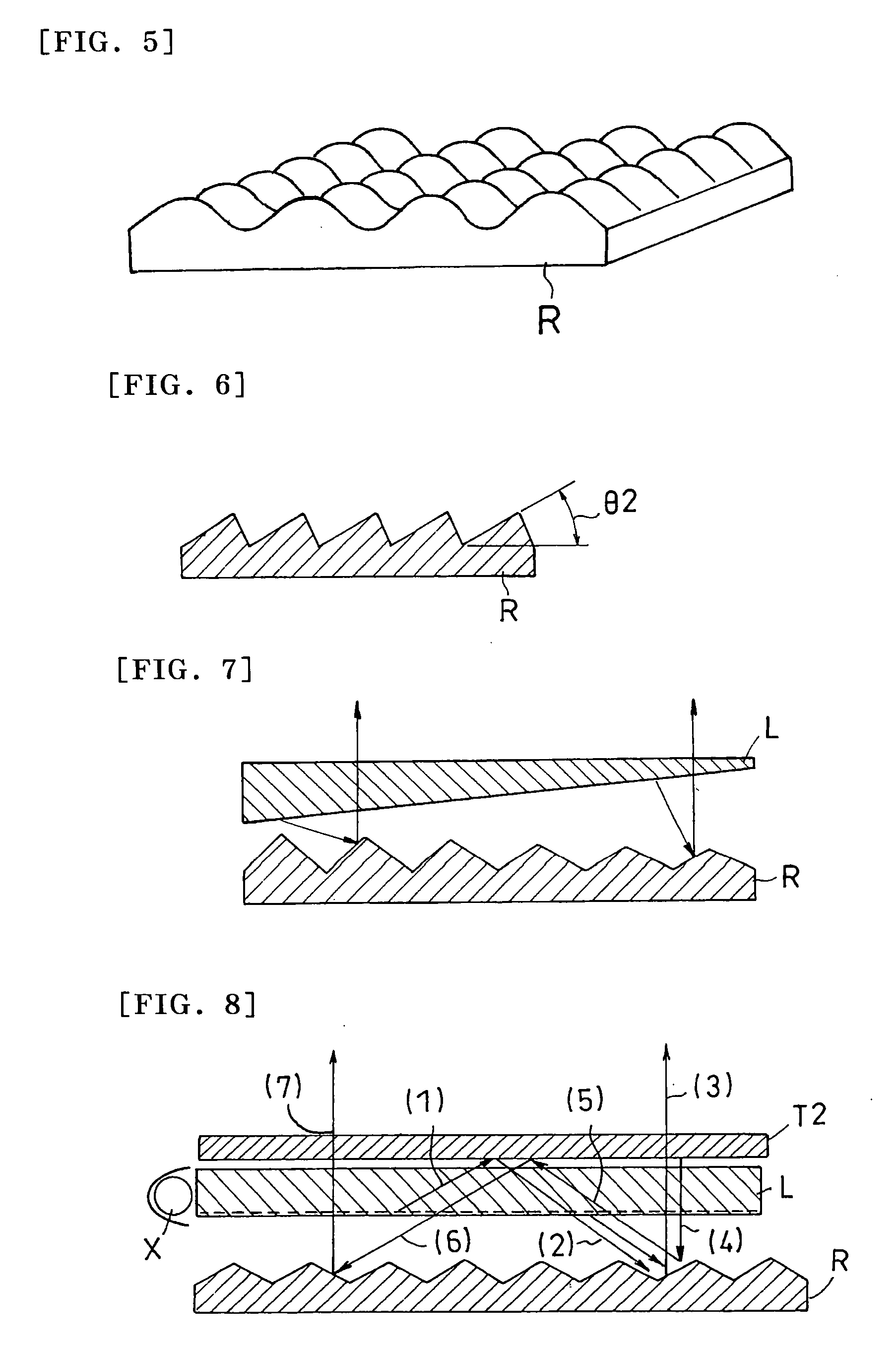
[0324] A reflection plate (R) was, in a first step, fabricated as a surface profile plate shown in FIG. 3 by emboss rolling a surface of a hard vinyl chloride plate (with a thickness of 1 mm) manufactured by Mitsubishi Plastic, Inc. The plate had a pitch of about 100 μm in raised portions. Aluminum was vacuum vapor deposited on the obtained surface profile to a thickness of 0.1 μm to thereby obtain a reflection plate with depressions and protrusions thereon. An average slope angle (θ2) of depressions and protrusions on the surface (repetitive slope structure) was about 35°.

[0325] Used as a transmittance angle dependent polarizing layer (T2) was a polarizing element (A) with a structure in which a retardation plate (b1) was inserted between linear polarization type reflec...

example 3

[0331] Used as a light guide plate (L) was a two lamp type sidelight light guide plate taken out of a light box (Light Pure-7000pro) manufactured by HakubaPhoto Industry Co., Ltd. A peak angle (θ1) in the emitting light direction was about 70°.

[0332] A reflection plate (R) was obtained as a reflection plate with a surface structure, which corresponds to that shown in FIG. 4 fabricated in a procedure in which a silver vapor deposited PET film (BL film, manufactured by Oike Industrial Co., Ltd., with a thickness of 50 μm) was folded at points with a pitch of 5 mm and the folded film was adhered on a cut aluminum substrate with a ridge repetitive surface structure each of which has a predetermined angle. An average slope angle (θ2) of the surface structure (a repetitive slope structure) was about 35°. The reflection plate exposes the PET substrate layer of the silver vapor deposited PET film on the front side, while adhering to the aluminum substrate by the vapor deposited surface, an...


PUM


Abstract

A light source comprising sidelight type backlight light guide plate (L), wherein a transmittance angle dependent layer (T1) which transmits normally incident light and reflects obliquely incident light is disposed on one surface of the sidelight type backlight light guide plate (L), and a reflection plate (R) having a repetitive slope structure is disposed on the other surface of the sidelight type backlight light guide plate (L). The invention light source is less in absorption loss due to repetition of light reflection and the like.

Description

TECHNICAL FIELD [0001] The invention relates to a light source and a liquid crystal display. BACKGROUND ART [0002] A mainstream light source on the market is of a design that a prism sheet (P) or the like is, as shown in FIG. 27, combined with a sidelight type light guide plate (L) having a diffuse reflection plate (R′) disposed below the light guide plate to thereby increase an incident component in the front direction. In the light source of FIG. 27, a diffusing plate (Y) is disposed above the prism sheet. Generally, a light emitting angle of a sidelight type light guide plate is an angle shallow relative to the upper side or lower side and of 60° or more from the front direction and light emitting angles are, in more of cases, distributed within a range of shallow angles of 70° or more from the front direction. Since a light guide plate of this kind guides light in a resin plate using a critical angle and light is taken out in a state outside the critical condition, lights emitti...

Claims


Application Information

Patent Timeline
IPC IPC(8): F21V7/04G02F1/1335F21V8/00F21Y103/00G02B5/30G02B6/00G02F1/13357G02F1/13363
CPCG02B6/0055G02B6/005
Inventor HARA, KAZUTAKATAKAHASHI, NAOKITAKEDA, KENTAROUSHIRAOGAWA, MIKI
Owner NITTO DENKO CORP
Why Eureka
Try Eureka