
Pallet content identification mechanism that converts RFID information to corresponding barcode information

a technology of rfid information and identification mechanism, which is applied in the direction of burglar alarm mechanical actuation, burglar alarm by hand-portable articles removal, etc., can solve the problems of not being able to benefit from rfid inventory control, distributors and retailers will be much slower to install rfid systems, and potential mismatch between rfid and existing barcode technologies

Active Publication Date: 2008-05-27
INT BUSINESS MASCH CORP
View PDF2 Cites 22 Cited by
  • Summary
  • Abstract
  • Description
  • Claims
  • Application Information

AI Technical Summary

Benefits of technology

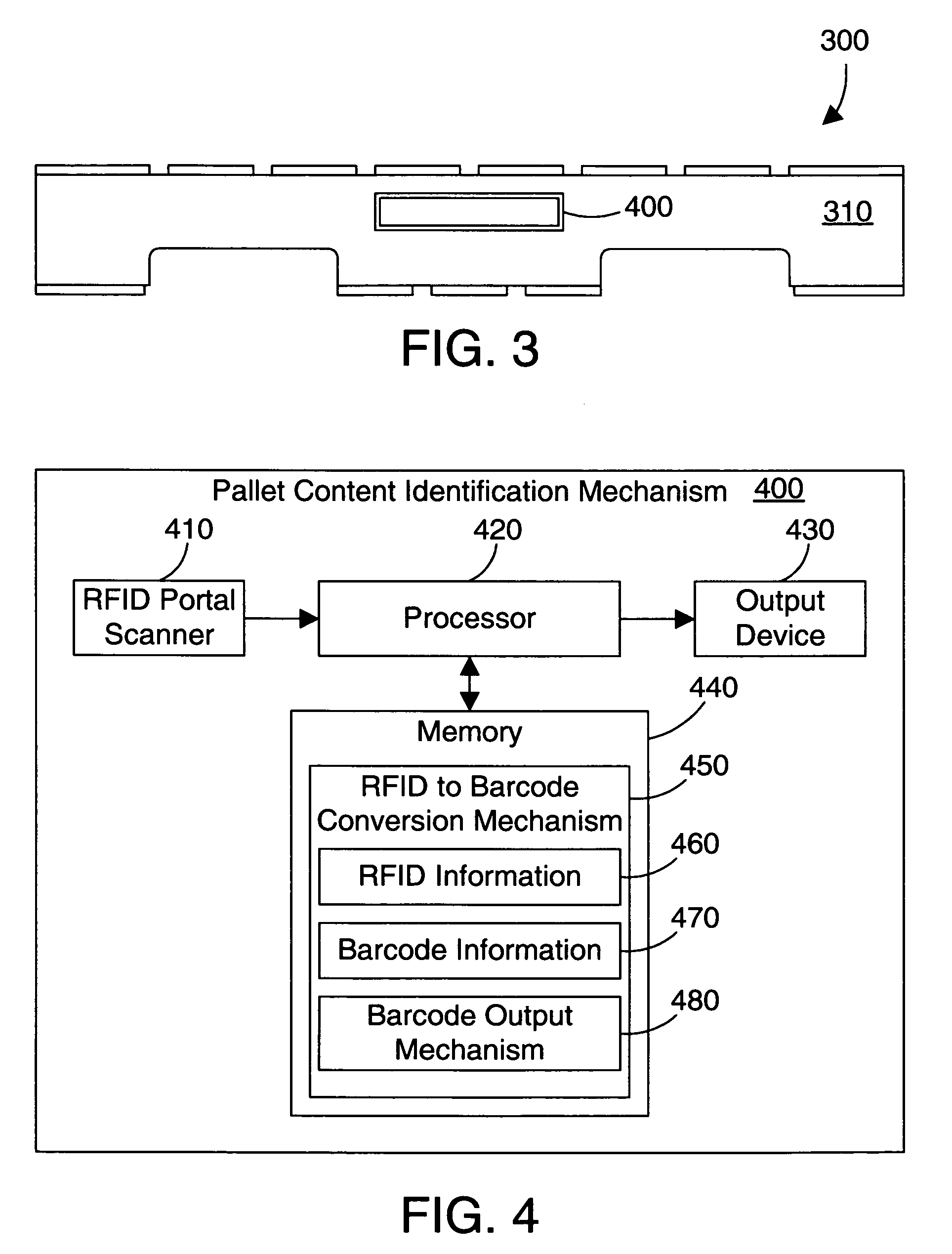
[0007]According to the preferred embodiments, a pallet content identification mechanism is a small electronic device that is attached to a pallet. The pallet content identification mechanism reads RFID tags on the pallet using an RFID portal scanner, converts the RFID information into corresponding barcode information, and displays the corresponding barcodes on a small display. These barcodes may then be scanned by a conventional barcode scanner, thereby allowing all of the items on the pallet to be scanned into the barcode system without unpacking the pallet. The pallet identification mechanism allows a user to benefit from RFID technology on the pallet while still using barcode technology in the inventory control system.

Problems solved by technology

As a result, many suppliers are rushing to install RFID systems.
While the adoption of RFID technology may be done quickly for large companies that have a large budget for converting their inventory control systems from barcode to RFID, many smaller companies, distributors, and retailers will be much slower to install RFID systems due to the relatively large cost of completely converting from barcode to RFID.
This creates a potential mismatch between RFID and existing barcode technologies.
Without a way to easily transfer RFID information into a barcode system without a large investment of capital, the smaller distributors and retailers will not be able to benefit from RFID inventory control until they completely convert to a full-blown RFID system, which may be prohibitively expensive.

Method used


Image

  • Pallet content identification mechanism that converts RFID information to corresponding barcode information
  • Pallet content identification mechanism that converts RFID information to corresponding barcode information
  • Pallet content identification mechanism that converts RFID information to corresponding barcode information

Examples


Embodiment Construction

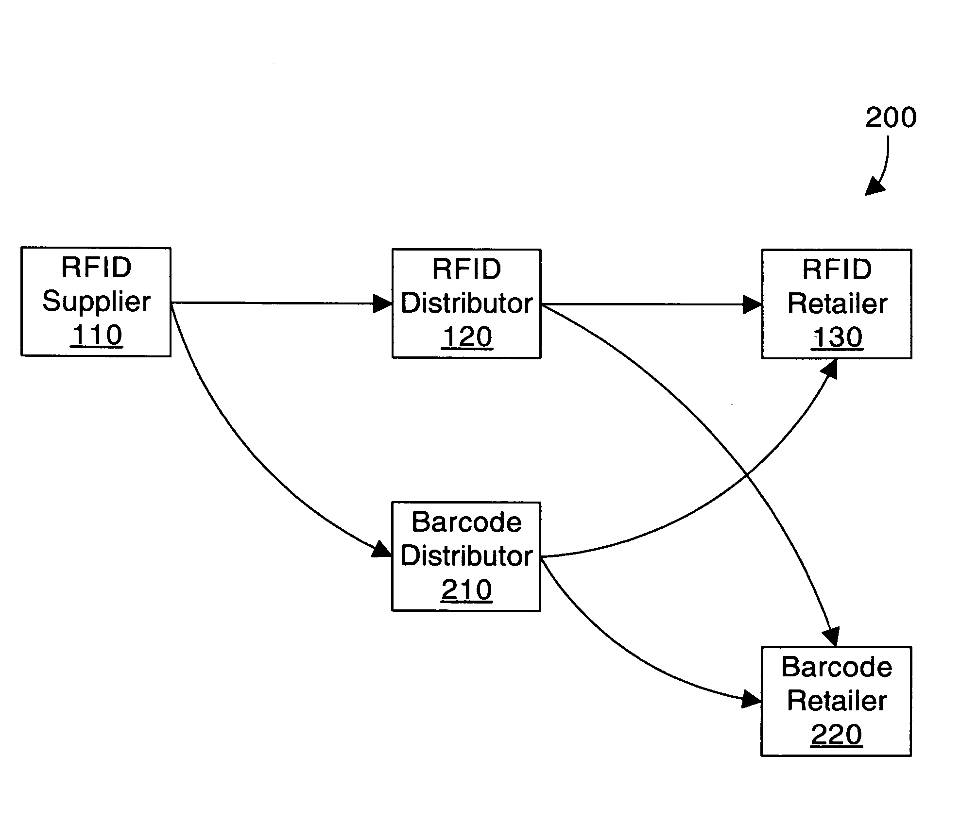
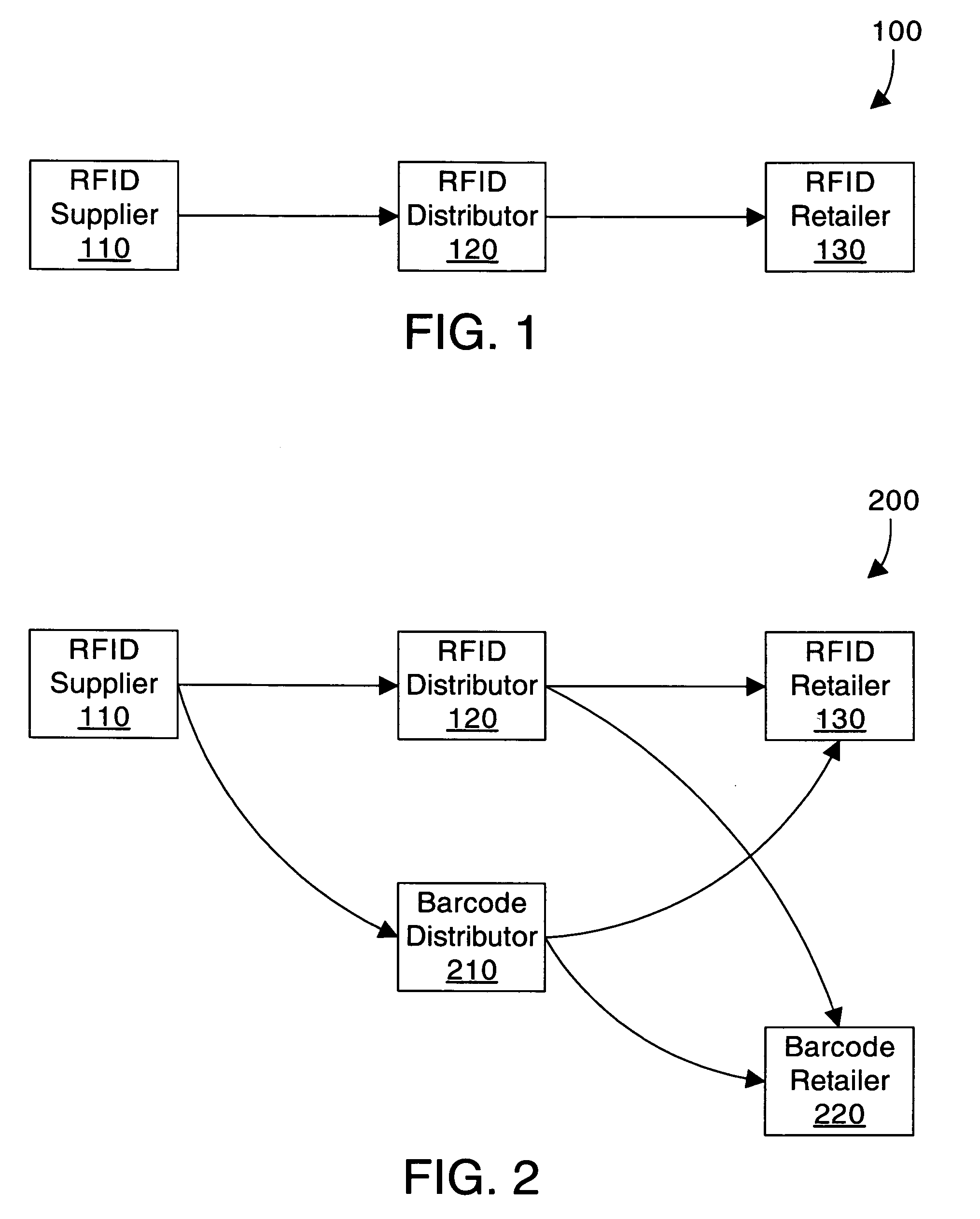
[0017]A pallet content identification mechanism provides a simple and easy-to-use bridge between RFID data and traditional barcode systems. The pallet content identification mechanism is attached to a pallet, and includes an RFID scanner that is capable of scanning RFID data for the items on the pallet. A RFID to barcode conversion mechanism reads the RFID data from the scanner, converts the RFID data into corresponding barcode information, and outputs the corresponding barcode information to a barcode-based inventory control system. In this manner the RFID data from the items on the pallet is converted and input into a barcode-based inventory control system. In one specific embodiment, the barcode information is output to a display on the pallet content identification mechanism, which may then be scanned by a traditional barcode scanner.

[0018]Referring to FIG. 1, an RFID supply chain is shown, and includes an RFID supplier 110 coupled to an RFID distributor 120, which is coupled to...


PUM


Abstract

A pallet content identification mechanism is a small electronic device that is attached to a pallet. The pallet content identification mechanism reads RFID tags on the pallet using an RFID portal scanner, converts the RFID information into corresponding barcode information, and displays the corresponding barcodes on a small display. These barcodes may then be scanned by a conventional barcode scanner, thereby allowing all of the items on the pallet to be scanned into the barcode system without unpacking the pallet. The pallet identification mechanism allows a user to benefit from RFID technology on the pallet while still using barcode technology in the inventory control system.

Description

BACKGROUND OF THE INVENTION[0001]1. Technical Field[0002]This invention generally relates to inventory control systems, and more particularly relates to using radio frequency identification (RFID) information in a barcode environment.[0003]2. Background Art[0004]Radio Frequency Identification (RFID) presents a new paradigm for inventory control. Each item that needs to be tracked is equipped with an RFID tag, which is a small, passive electronic device that may be attached to or embedded into a product or its packaging. In an RFID system, a scanner sends out radio-frequency energy. This radio-frequency energy provides power to the RFID tags. In response, the RFID tags transmit their identifying information. RFID thus allows an entire pallet or truck to be scanned, thereby providing easy inventory control. An RFID system may also include active emitters with a battery that allows the RFID tag itself to transmit the signal instead of the scanner providing the power via the radio frequ...

Claims


Application Information

Patent Timeline
Patent Type & Authority Patents(United States)
IPC IPC(8): H04Q5/22
CPCG06K1/18G06K7/1095G06Q10/087G08B13/14G08B13/24
Inventor JENNEY, ERIC H.WEAVER, MATTHEW RYAN
Owner INT BUSINESS MASCH CORP
Learn More