
Stair climbing platform apparatus and method

a platform and stair technology, applied in the field of vehicles, can solve the problems the difficulty of the wheeled platform navigating over uneven terrain, and the difficulty of the wheeled platform traversing obstacles, etc., and achieves the effect of increasing the power requirements of the system and the complexity of the robotic system outside the modern factory floor

Inactive Publication Date: 2008-06-03
GAMMA TWO
View PDF28 Cites 40 Cited by
  • Summary
  • Abstract
  • Description
  • Claims
  • Application Information

AI Technical Summary

Benefits of technology

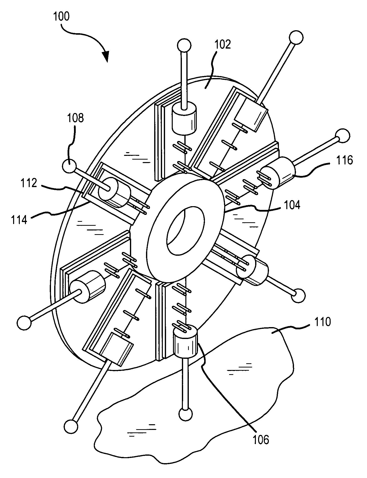
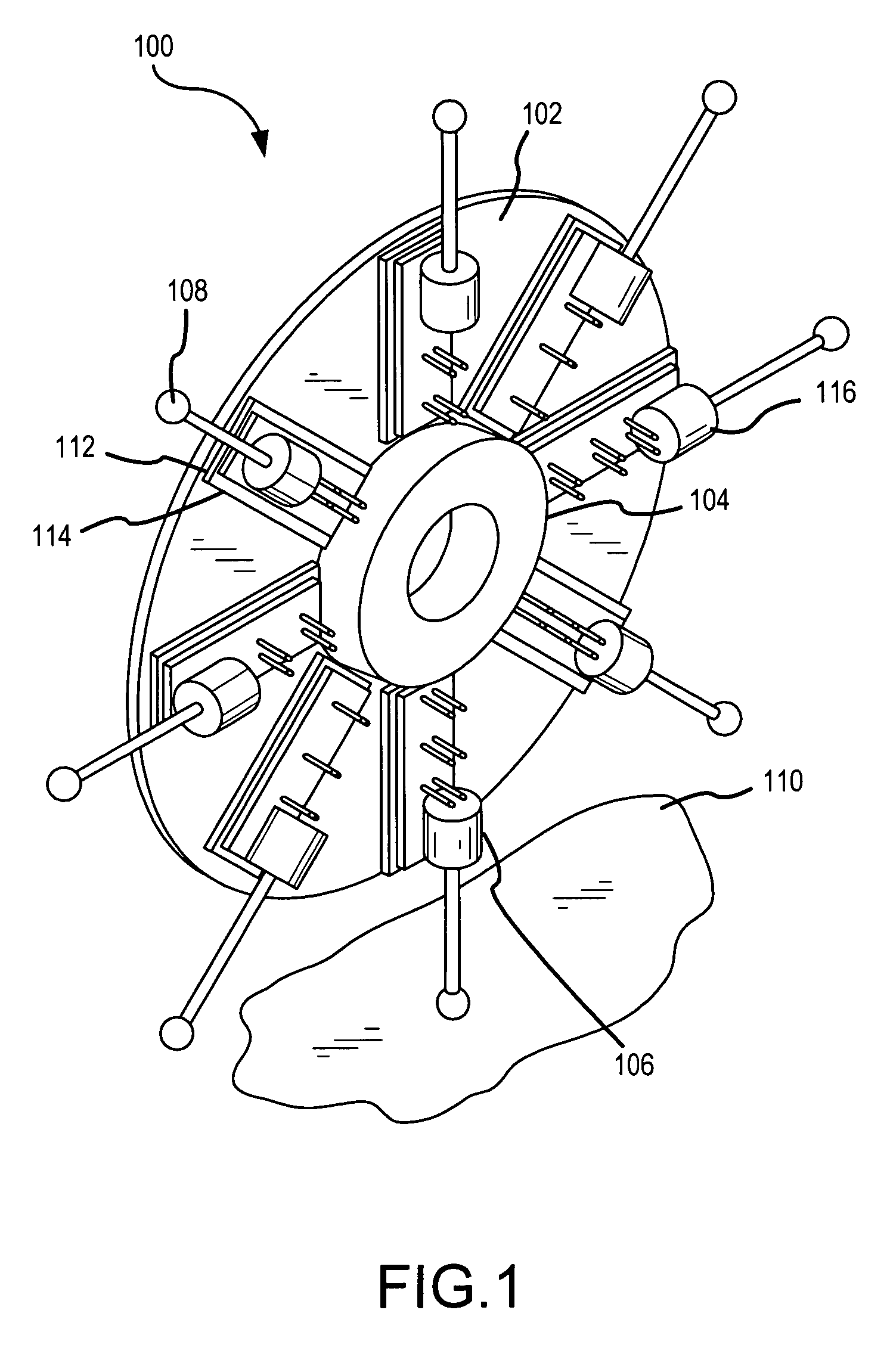
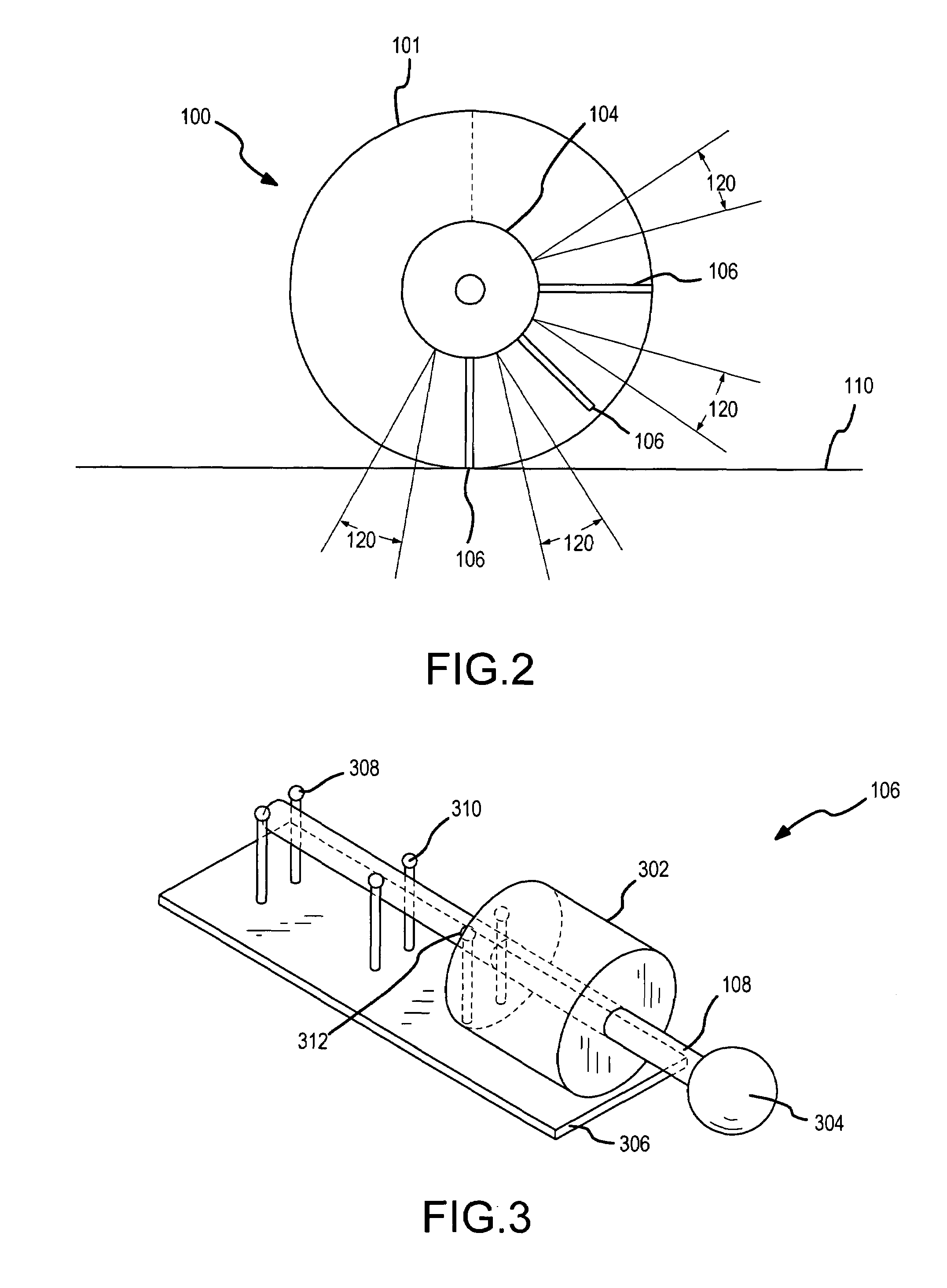
[0008]The hub functions as the mounting point for the intelligent wheel and, in one embodiment, a disc fastened to the hub provides structural support for the other components such as each retractable spoke mechanism including a proximity sensor, distance sensor, and force detector for each spoke. The central portion of the hub is preferably mechanically connected to a driven axle to provide rotational driving force for the platform vehicle. In addition to the mechanical coupling, the central portion of the hub may optionally provide an electrical connection from a power source mounted on the vehicle platform to supply electrical power to the hub mounted electrical components. In the intelligent wheel in accordance with an embodiment of the present invention, the spokes are active. These active spokes extend and retract in response to force, distance and position signals from the various sensors associated with each spoke mechanism. These spoke mechanisms are controlled by an automated microprocessor or microcontroller control system that may be mounted on the wheel itself or the vehicle platform. This allows the wheel to adapt to and negotiate over obstacles and voids in the surface over which it is traveling.

Problems solved by technology

Today, there are increasingly complex demands for robotic systems outside a modern factory floor.
One significant problem, at present, is that wheeled platforms have difficulty navigating over uneven terrain, and traversing obstacles.
While significant work has been done on bipedal and multi-legged robots, these systems typically have much higher power requirements than wheeled platforms.
However, wheels are only efficient if the surface over which they travel is flat and relatively smooth, and wheels fail if there are either vertical obstacles, or significant voids in the surface.
Hence, wheels have shown their worth in carefully engineered environments, and have failed in more complex domains.
Such uneven terrain may include vertical discontinuities, steps, and stairs, and situations where those surfaces are potentially covered with a variety of debris.
For instance, if a traditional wheel were approaching a curb from the road surface, the curb would present a vertical obstacle, over which the wheel would have to climb.
However, as the radius of the wheel approaches the height of the curb, the energy transfer becomes less effective, until the wheel fails to climb obstacles that exceed its radius.
Currently there is no mechanism that provides generally passive support for the platform to which it is attached, provides power for movement over surfaces, and can provide movement across a wide variety of surfaces, including those found in rough terrain, urban environments, indoors, and disrupted and partially engineered settings.

Method used


Image

  • Stair climbing platform apparatus and method
  • Stair climbing platform apparatus and method
  • Stair climbing platform apparatus and method

Examples


Embodiment Construction

[0021]An intelligent wheel 100 in accordance with one embodiment of the present invention is shown in FIGS. 1-9. Referring now to FIG. 1, this wheel 100 has a generally disc shaped support portion 102, a central hub 104 about the center of the support portion 102, and a series of radial spoke mechanisms 106 fastened to the support portion 102 and positioned equally spaced around the central hub 104. The spoke mechanisms 106 are dynamically controlled by a controller that controls extension of the spoke or spokes 108 which are supporting the hub 104 at any given time so as to effectively increase or decrease the wheel radius, thus raising or lowering the center of mass of the wheel 100 and its load as it approaches and encounters an obstacle or change in the surface 110 on / over which it is traveling. In addition, the adjacent spoke or spokes 108, which is / are rotating down toward and onto the obstacle, can be extended, such as is shown in FIG. 7, such that they provide a grip point f...


PUM


Abstract

A platform wheeled apparatus that incorporates an intelligent wheel configuration for each wheel in which each wheel can dynamically change its radius to negotiate various obstacles. The intelligent wheel has a rotational hub and support disc that carries a series of arcuately spaced extendable, weight bearing radial spoke mechanisms that can be controllably extended and retracted in response to the anticipated terrain surface over which the wheel is to travel. The hub of the intelligent wheel carries a microcontroller for a set of obstacle proximity sensors, force and position sensors and an appropriate electrical power supply for operation of the spokes and control components.

Description

BACKGROUND OF THE INVENTION [0001]1. Field of the Invention[0002]This invention generally relates to vehicles and more particularly to a platform vehicle that can negotiate obstacles such as stairs.[0003]2. Description of Related Art[0004]Today, there are increasingly complex demands for robotic systems outside a modern factory floor. One significant problem, at present, is that wheeled platforms have difficulty navigating over uneven terrain, and traversing obstacles. While significant work has been done on bipedal and multi-legged robots, these systems typically have much higher power requirements than wheeled platforms. Wheeled platforms are, perhaps, the most efficient mechanisms for moving across any surface. Legged platforms require power both to move the platform horizontally across the surface, and require additional power to both support the platform and to lift and move the legs themselves. The wheel provides a passive support to the load, negating the need for the power n...

Claims


Application Information

Patent Timeline
Patent Type & Authority Patents(United States)
IPC IPC(8): B62D57/00B62D51/06
CPCB62D49/0635B62D57/022
Inventor GUNDERSON, LOUISE F.BROWN, CHRISTIANGUNDERSON, JAMES P.
Owner GAMMA TWO
Learn More