Modular inflatable multifunction field-deployable apparatus and methods of manufacture

a multi-functional, modular technology, applied in lighting and heating apparatus, instruments, lighting and daylight use, etc., can solve the problems of plurality of losses, prior art neither contemplates nor anticipates such elements or benefits, and all related art is significantly more limited in respect, so as to minimize air, water and ground pollution and high environmental protection

Inactive Publication Date: 2008-06-03
ESSIG JR JOHN RAYMOND +1
View PDF59 Cites 37 Cited by
  • Summary
  • Abstract
  • Description
  • Claims
  • Application Information

AI Technical Summary

Benefits of technology

[0118]An eighth main object of the invention is to provide a portable multifunctional apparatus that is highly environmentally friendly by virtue of the fact that the apparatus generally requires no fuel to operate. Instead, the instant invention typically relies solely on radiating solar energy when used for heating, cooking, and the like, thereby minimizing air, water, and ground pollution. This is in stark contrast to other common portable cooking and heating equipment, which generally rely on the combustion of hydrocarbon fuels and, thus, inherently cause pollution through both combustion processes and unintentional fuel releases (e.g., spills, leaks, vapor releases, and the like).
[0119]It is a further object of the invention to provide improved elements and arrangements thereof for the purposes described which is inexpensive, dependable, and fully effective in accomplishing its intended purposes.

Problems solved by technology

In contrast, all related art is significantly more limited with respect to utilities and applications thereof.
In contrast, except for the occasional use of well-known focal point supports, prior art neither contemplates nor anticipates such elements or the benefits thereof.
In contrast, most related art requires sunlight or other electromagnetic radiation to pass through the transparent membrane of a super-ambient reflector chamber on its way to and from the reflector, thereby resulting in a plurality of losses.
The remaining prior art, although utilizing a sub-ambient pressure reflector chamber, also requires the electromagnetic energy to pass through at least one intervening layer, such as a radome, again resulting in a plurality of losses.
Ultimately, the intervening layers of prior art are typically responsible for reducing the efficiency of such devices by as much as twenty percent, or more, depending upon the wavelength of the impinging radiation and the transmission characteristics of the material or materials comprising the intervening layer.
In contrast, the related art provides no such means for conveniently maintaining the apparatus in the field.
This is in stark contrast to other common portable cooking and heating equipment, which generally rely on the combustion of hydrocarbon fuels and, thus, inherently cause pollution through both combustion processes and unintentional fuel releases (e.g., spills, leaks, vapor releases, and the like).

Method used


Image

  • Modular inflatable multifunction field-deployable apparatus and methods of manufacture
  • Modular inflatable multifunction field-deployable apparatus and methods of manufacture
  • Modular inflatable multifunction field-deployable apparatus and methods of manufacture

Examples


second embodiment

FIGS. 4A–C Description and Operation of the Basic Inflatable Reflector Apparatus—Second Embodiment

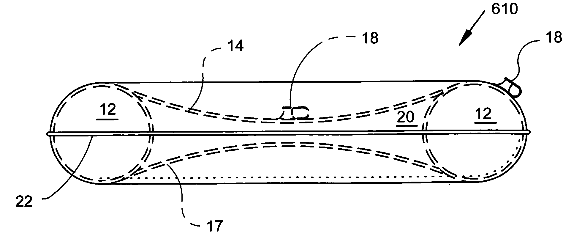
[0183]In FIG. 4A, the second main embodiment device 386 is illustrated as an inflated toroid or ring support element 400 supporting an upper transparent membrane 388 and a lower reflective membrane 390. The transparent membrane 388 and reflective membrane 390 provide a central reflector chamber (i.e., pressure envelope) 392 with a double parabolic convex—convex lens configuration when inflated to a super-ambient pressure. The transparent membrane 388 has a centered inflation valve 18 for inflating the reflector chamber 392; however, it is noted that the inflation valve 18 may alternatively be located at any other useful location such as in the reflective membrane 390. The inflatable toroidal support element 400 also has a valve 18 for inflation to form a rigid ring. Two valves are shown for separate inflation of the ring support 400 and the reflector chamber 392; however, it is noted th...


PUM


Abstract

An modular, inflatable, multifunction, multipurpose, parabolic reflector apparatus having a plurality of manufactured parabolic mirrors made from a pressure-deformable reflective covering of an inflatable ring for focusing electromagnetic energy from radio frequency radiation (RF) through the ultraviolet radiation (UV) and solar energy for (1) heating and cooking, for (2) electrical power generation, for (3) enhancing the transmission and reception of radio signals, for (4) enhancing vision in low-light environments, and for (5) projection of optical signals or images. The device also has non-electromagnetic uses, such as the collection of water. A first main embodiment utilizes two reflective membranes. A second main embodiment utilizes a reflective membrane and a transparent membrane. Portability is enhanced by complete collapsing of the inflatable device.

Description

CROSS-REFERENCE TO RELATED APPLICATIONS[0001]This application is a continuation-in-part of U.S. patent application Ser. No. 10 / 156,814, filed 30 May 2002 (now U.S. Pat. No. 6,897,832 issued 24 May 2005), which is related to U.S. Provisional Patent Application Ser. No. 60 / 294,440 filed May 30, 2001. This application relates to co-pending PCT Patent Application Serial No. PCT / US02 / 16918 as filed May 30, 2002, as amended Nov. 27, 2002 under PCT Article 19, and as amended Dec. 30, 2002 under PCT Article 34. The entire specification (including Description, Drawing, and Claims) contained within each of these related applications (e.g., U.S. patent application Ser. No. 10 / 156,814; U.S. Provisional Patent Application Ser. No. 60 / 294,440; and PCT Patent Application Serial No. PCT / US02 / 16918), both as filed and as amended (where applicable), is hereby incorporated herein by reference.BACKGROUND OF THE INVENTION[0002]1. Field of the Invention[0003]The present invention relates most broadly to ...

Claims


Application Information

Patent Timeline
Patent Type & Authority Patents(United States)
IPC IPC(8): H01Q1/12H01Q15/20F21S11/00F21S13/12F21V7/16F21V7/18F24J2/52F24S20/30F24S23/71G02B26/08G10K11/28H01Q1/34H01Q15/16
CPCF21S11/00F21S13/12F24J2/02F24J2/125G02B26/0825G10K11/28H01Q1/34H01Q15/163F24J2/5271F21V7/16F21V7/18Y02B40/18Y02E10/42Y02E10/47F24S20/80F24S23/715F24S20/30F24S50/20Y02E10/40
Inventor ESSIG, JR., JOHN RAYMONDESSIG, JAMES MICHAEL
Owner ESSIG JR JOHN RAYMOND
Why Eureka
Try Eureka