
Disc based alt-azimuth telescope mount

a telescope mount and disc technology, applied in the field of telescope mounts, can solve the problems of not being able to carry telescopes of varying widths, not being able to handle telescopes of varying sizes, and not being able to mount telescopes

Active Publication Date: 2008-06-03
PETERS JR LYAL T
View PDF3 Cites 12 Cited by
  • Summary
  • Abstract
  • Description
  • Claims
  • Application Information

AI Technical Summary

Benefits of technology

[0012]An object of the present invention is to provide a disc based alt-azimuth telescope mount that permits the magnitude of friction to be easily adjusted between discs.
[0024]An additional object of the present invention is to provide a disc based alt-azimuth telescope mount that does not require locks during the use of slow motion controls.

Problems solved by technology

Unfortunately, existing alt-azimuth telescope mounts have proven to be quite amendable to vibrations and do not remain rigid to outside forces such as wind or touch.
Although adding a second arm has reduced this problem somewhat, it has lead to a host of other design deficiencies, such as not being able to carry telescopes of varying widths.
One notable drawback found in existing alt-azimuth telescope mounts is that they are not able to handle telescopes of varying sizes without the addition of counter-balance devices and do not permit the mount to swing freely without interference from the telescope hitting the base of the mount.
A further problem encountered with existing alt-azimuth telescope mounts is that they are not able to handle various size loads such as cameras, eyepieces and the like without unwanted movement caused by imbalance.
These mechanisms, however, have generally proven cumbersome and inadequate in practice because the mount axis must be locked during use.
Similarly, friction locks have not adequately addressed this issue.
Additionally, existing mounts often do not maintain all axes and planes perfectly orthogonal with each other as required for accuracy when electronic shaft encoders are utilized with computerized locaters, commonly known in the art as setting circles.
Significant errors are introduced where the axes of the telescope mount are not perfectly orthogonal.

Method used


Image

  • Disc based alt-azimuth telescope mount
  • Disc based alt-azimuth telescope mount
  • Disc based alt-azimuth telescope mount

Examples


Embodiment Construction

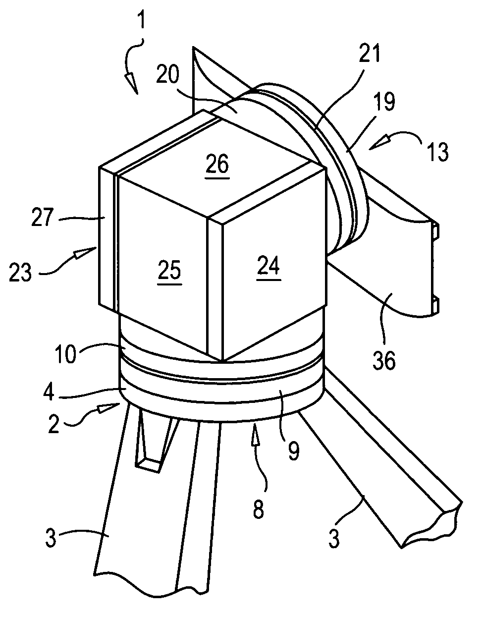
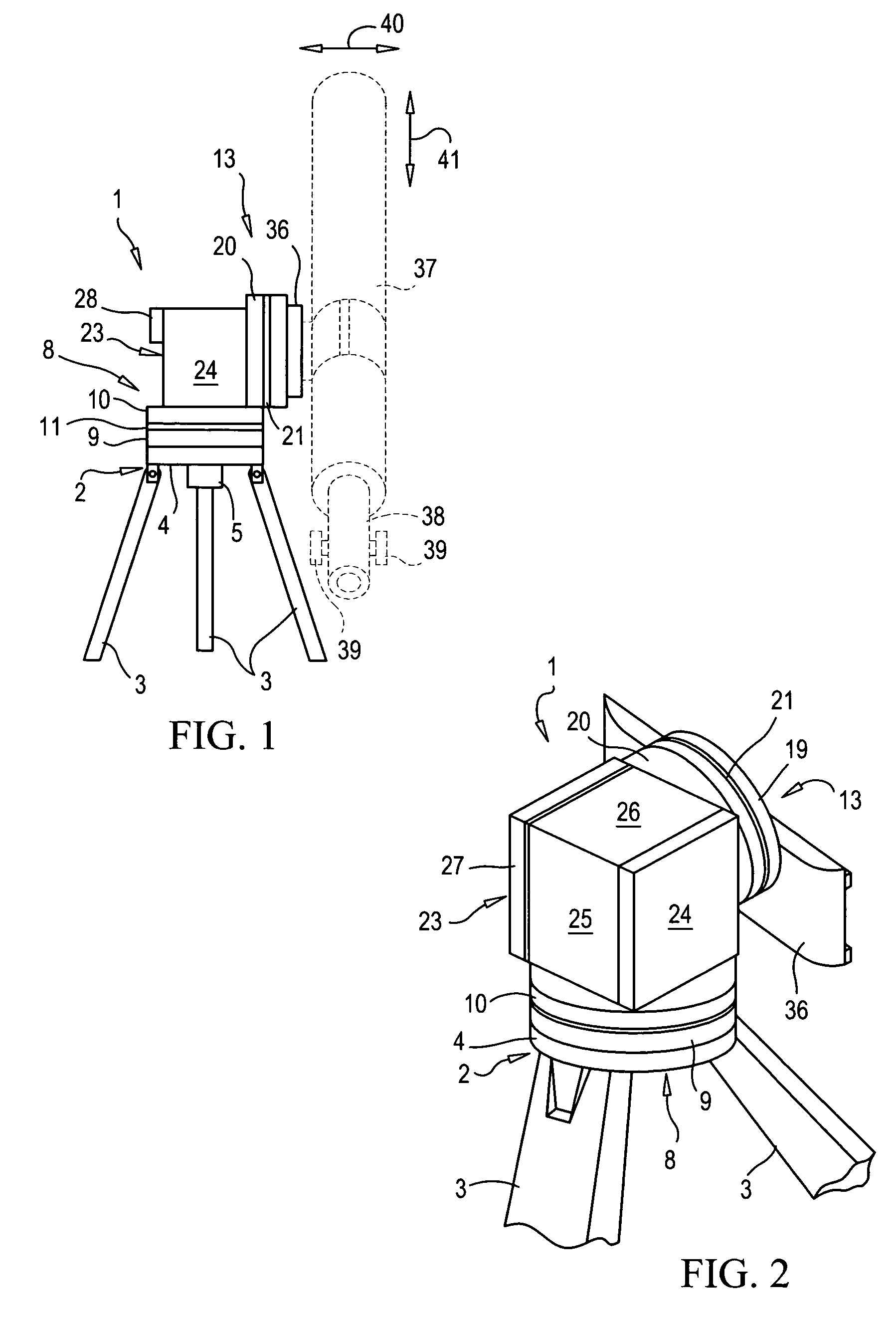
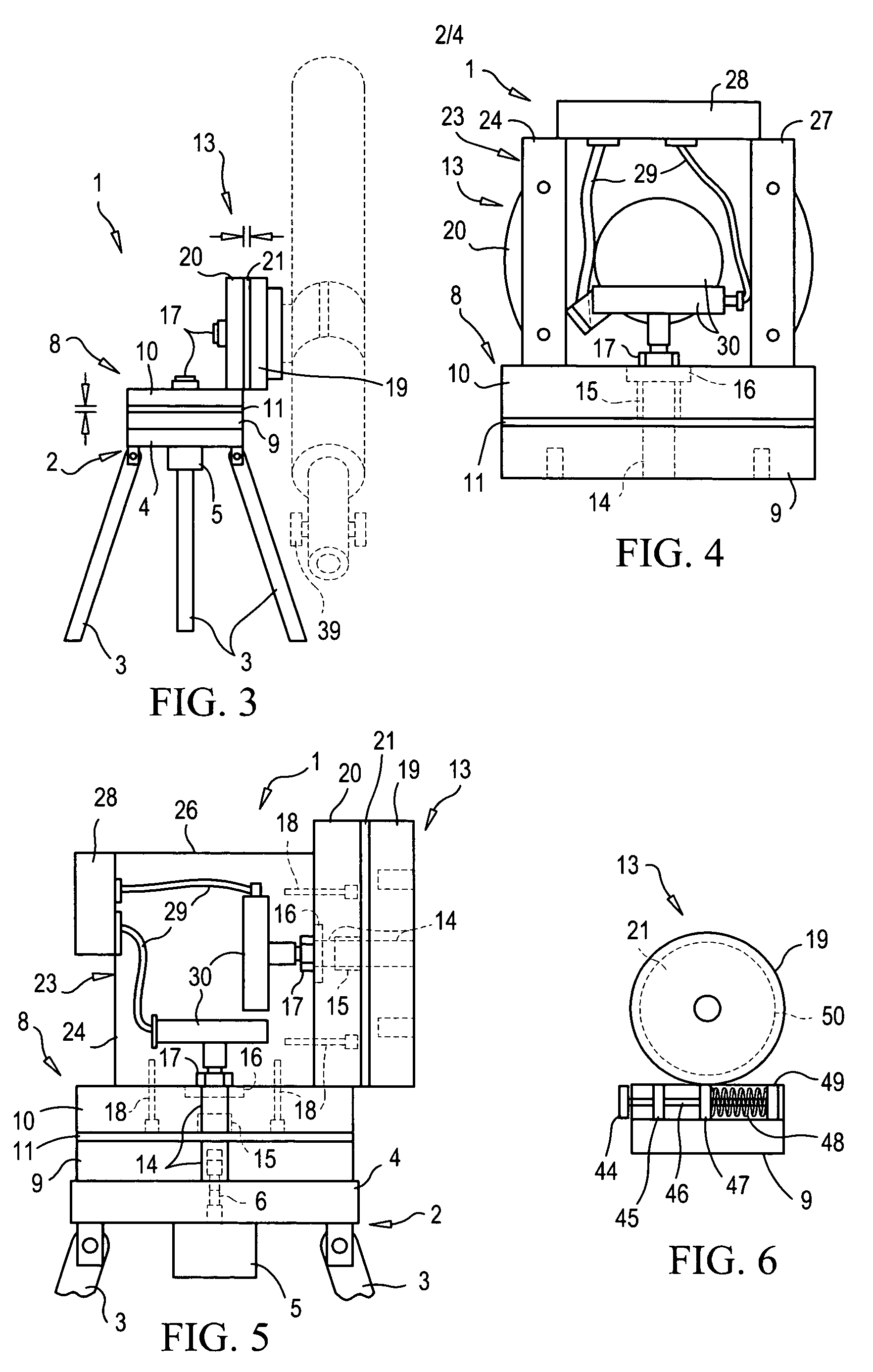
[0041]Shown throughout the figures, the present invention is generally directed towards a disc based alt-azimuth telescope mount for use with any of a variety of existing telescopes.

[0042]Referring initially to FIG. 10, a prior art equatorial telescope mount 70, provided on a tripod 75, is shown. As shown in the Figure, the telescope mount 70 of the prior art includes a lower or right ascension axis 71 disposed at an angle to the observer's latitude 72 and pointed north (northern hemisphere) or south (southern hemisphere). This places the telescope 73 at the same plane as the earth, which allows the telescope 73 to follow a curve equal to the celestial curve at the observer's location, making it possible for the telescope 73 to track celestial objects as the earth spins with a single movement of the right ascension axis 71 (east-west movement) while the declination axis 74 (north-south movement) remains stationary while the object is being observed.

[0043]A prior art altitude-azimuth...


PUM


Abstract

A disc-based altitude-azimuth telescope mount for mounting and adjusting a telescope along altitude and azimuth axes. The telescope mount includes an azimuth disc assembly for facilitating adjustment of the telescope along the azimuth axis and an altitude disc assembly for facilitating adjustment of the telescope along the altitude axis. A friction adjusting mechanism operably engages the azimuth disc assembly and the altitude disc assembly to prevent inadvertent movement of the telescope along both axes. A digital setting circle may be operably connected to the disc assemblies to facilitate automatic adjustment of the telescope, as desired.

Description

CROSS-REFERENCE TO RELATED APPLICATIONS[0001]This application claims the benefit of U.S. Provisional Patent Application No. 60 / 445,991, filed Feb. 6, 2003, and U.S. Non-Provisional patent application Ser. No. 10 / 772,986, filed Feb. 5, 2004, both of which are incorporated by reference herein in their entireties.BACKGROUND OF THE INVENTION[0002]1. Field of the Invention[0003]The present invention relates generally to telescope mounts, and more particularly, to a disc-based alt-azimuth mount for telescopes.[0004]2. Description of the Prior Art[0005]A wide variety of telescope mounts are available for both astronomical and non-astronomical telescopes. These generally fall under two broad categories, namely equatorial and altitude-azimuth mounts. Equatorial mounts are designed to follow the celestial sphere by moving the telescope in one axis only. An alt-azimuth mount, on the other hand, is designed to move in two axes to follow both the celestial sphere and the vertical altitude dimens...

Claims


Application Information

Patent Timeline
IPC IPC(8): G02B23/00
CPCG02B23/16
Inventor PETERS, JR., LYAL T.
Owner PETERS JR LYAL T
Learn More